15.1.2 Lab – Implement NTP Answers
Lab – Implement NTP (Answers Version)
Answers Note: Red font color or gray highlights indicate text that appears in the instructor copy only.
Topology
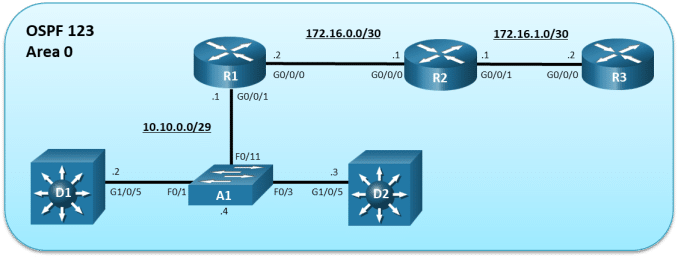
Addressing Table
|
Device |
Interface |
IPv4 Address |
|
R1 |
G0/0/0 |
172.16.0.2/30 |
|
R1 |
G0/0/1 |
10.10.0.1/29 |
|
R2 |
G0/0/0 |
172.16.0.1/30 |
|
R2 |
G0/0/1 |
172.16.1.1/30 |
|
R3 |
G0/0/0 |
172.16.1.2/30 |
|
D1 |
G1/0/5 |
10.10.0.2/29 |
|
D2 |
G1/0/5 |
10.10.0.3/29 |
|
A1 |
VLAN 1 |
10.10.0.4/29 |
Objectives
Part 1: Build the Network, Configure Basic Device Settings and Routing
Part 2: Configure NTP in a P2P Network
Part 3: Configure NTP in a Multiaccess Broadcast Network
Background / Scenario
Many router and switch features require an accurate time source to operate efficiently. Synchronized timestamps are important for troubleshooting purposes, Syslog and SNMP event reporting, and for the correlation of security-based events across multiple devices.
Some devices use a software clock that is reset whenever the device is rebooted. Therefore, the date and time would have to be manually re-entered every time the device is restarted. Other devices use a hardware clock that can retain the time even when restarted. Regardless, each device clock would never really be synchronized with other devices. A better, scalable solution is required.
NTP is a scalable solution to synchronize the time on multiple network devices. NTP creates a hierarchical architecture using authoritative time sources to synchronize clients. An NTP client occasionally polls an NTP server and multiple NTP messages increase accuracy.
Note: NTP uses UDP port 123 and is documented in RFC 1305. Current versions include NTPv3 and NTPv4.
NTP is commonly implemented in three ways depending on the network type:
- Point-to-point (P2P) – Consists of an NTP server (master) and NTP client.
- Broadcast – Consists of an NTP server broadcasting (i.e., multicasting) to listening NTP broadcast clients. The server is configured using the ntp broadcast interface command and clients are configured using the ntp broadcast client interface command.
- NTP Peers – Used in larger redundant topologies for backup purposes where two NTP servers are also peers to query different external time sources. The peers establish a client server relationship with each other and try to offer their clock settings to each other. NTP peers are configured using the ntp peer peer-ip-address global config command.
In this lab, you will configure NTP as follows:
- R3 will be the designated authoritative time source.
- R2 and R3 will establish a P2P client-server NTP connection while R1 and R2 will establish a P2P client-server NTP connection.
- R1 will be configured as an NTP broadcast server to the NTP broadcast clients (i.e., A1, D1, and D2).
Note: This lab is an exercise in developing, deploying, and verifying how NTP operates and does not reflect networking best practices.
Note: The routers used with this CCNP hands-on lab are Cisco 4221and the two Layer 3 switches are Catalyst 3650 switches. Other routers and Layer 3 switches and Cisco IOS versions can be used. Depending on the model and Cisco IOS version, the commands available and the output produced might vary from what is shown in the labs.
Note: Ensure that the routers and switches have been erased and have no start–up configurations. If you are unsure contact your instructor.
Answers Note: Refer to the Answers Lab Manual for the procedures to initialize and reload devices.
Required Resources
- 3 Routers (Cisco 4221 with Cisco IOS XE Release 16.9.4 universal image or comparable)
- 2 Switches (Cisco 3650 with Cisco IOS XE release 16.9.4 universal image or comparable)
- 1 Switch (Cisco 2960 with Cisco IOS release 15.2(2) lanbase image or comparable)
- 1 PC (Choice of operating system with a terminal emulation program installed)
- Console cables to configure the Cisco IOS devices via the console ports
- Ethernet cables as shown in the topology
Instructions
Part 1:Build the Network, Configure Basic Device Settings and Routing
In Part 1, you will set up the network topology and configure basic settings and interface addressing on the routers, Layer 3 switches, and the Layer 2 switch. You will also configure multiarea OSPFv2 on the routers and Layer 3 switches.
Step 1:Cable the network as shown in the topology.
Attach the devices as shown in the topology diagram, and cable as necessary.
Step 2:Configure basic settings for the routers.
- Console into each router, enter global configuration mode, and apply the basic settings, interface addressing, and OSPFv2 configuration. A command list for each router is provided below for initial configurations.
Open configuration window
Note: Routers were configured with OSPFv2 using the interface configuration method.
Router R1
hostname R1
no ip domain lookup
line con 0
logging sync
exec-time 0 0
exit
banner motd # This is R1, Implement NTP Lab #
interface g0/0/0
ip add 172.16.0.2 255.255.255.252
ip ospf 123 area 0
no shut
exit
interface GigabitEthernet0/0/1
ip address 10.10.0.1 255.255.255.248
ip ospf 123 area 0
no shut
exit
Router R2
hostname R2
no ip domain lookup
line con 0
logging sync
exec-time 0 0
exit
banner motd # This is R2, Implement NTP Lab #
interface g0/0/0
ip add 172.16.0.1 255.255.255.252
ip ospf 123 area 0
no shut
exit
interface GigabitEthernet0/0/1
ip address 172.16.1.1 255.255.255.252
ip ospf 123 area 0
no shut
exit
Router R3
hostname R3
no ip domain lookup
line con 0
logging sync
exec-time 0 0
exit
banner motd # This is R3, Implement NTP Lab #
interface g0/0/0
ip address 172.16.1.2 255.255.255.252
ip ospf 123 area 0
no shut
exit
- Save the running configuration to startup-config.
Close configuration window
Step 3:Configure basic settings for the Layer 3 switches.
- Console into each Layer 3 switch, enter global configuration mode, and apply the basic settings and interface addressing. A command list for each switch is provided below for the initial configurations.
Open configuration window
Note: Switches were configured with OSPFv2 using the interface method.
Switch D1
hostname D1
no ip domain lookup
line con 0
exec-timeout 0 0
logging synchronous
exit
banner motd # This is D1, Implement NTP Lab #
ip routing
interface g1/0/5
no switchport
ip address 10.10.0.2 255.255.255.248
ip ospf 123 area 0
no shut
exit
Switch D2
hostname D2
no ip domain lookup
line con 0
logging sync
exec-time 0 0
exit
banner motd # This is D2, Implement NTP Lab #
ip routing
interface g1/0/5
no switchport
ip address 10.10.0.3 255.255.255.248
ip ospf 123 area 0
no shut
exit
- Save the running configuration to startup-config.
Close configuration window
Step 4:Configure basic settings for the Layer 2 switch.
- Console into the Layer 2 switch, enter global configuration mode, and apply the basic settings and interface addressing. The command list is listed below for initial configurations.
Open configuration window
Switch A1
hostname A1
no ip domain lookup
line con 0
exec-timeout 0 0
logging synchronous
exit
banner motd # This is A1, Implement NTP Lab #
interface vlan 1
ip address 10.10.0.4 255.255.255.248
no shut
exit
ip default-gateway 10.10.0.1
- Save the running configuration to startup-config.
Close configuration window
Step 5:On D1, verify end-to-end connectivity and time.
- From D1, ping the R3 IP address (i.e., 172.16.1.2).
Open configuration window
D1# ping 172.16.1.2
Type escape sequence to abort.
Sending 5, 100-byte ICMP Echos to 172.16.1.2, timeout is 2 seconds:
!!!!!
Success rate is 100 percent (5/5), round-trip min/avg/max = 1/2/8 ms
There is end-to-end connectivity up to R3.
- Verify the time on D1 using the show clock command.
D1# show clock
*00:27:00.528 UTC Mon Mar 1 1993
Notice the time reference on D1 is not accurate.
Close configuration window
Step 6:On D2, verify end-to-end connectivity and time.
- From D2, ping the R3 IP address (i.e., 172.16.1.2).
Open configuration window
D2# ping 172.16.1.2
Type escape sequence to abort.
Sending 5, 100-byte ICMP Echos to 172.16.1.2, timeout is 2 seconds:
!!!!!
Success rate is 100 percent (5/5), round-trip min/avg/max = 1/2/8 ms
There is end-to-end connectivity up to R3.
- Verify the time on D2 using the show clock command.
D2# show clock
*00:29:25.759 UTC Mon Mar 1 1993
The time on D2 is also not accurate.
Close configuration window
Step 7:On A1, R1 and R2, verify end-to-end connectivity and time.
Open configuration window
- From A1, R1, and R2 verify that they have connectivity to R3.
- Verify their time.
Close configuration window
Part 2:Configure NTP in a P2P Network
In this part, NTP will be configured for P2P. Specifically, R3 will be the authoritative server for R2, and R2 will be the server for R1.
The device selected as the authoritative time server is configured using the ntp master stratum global configuration command. The stratum variable identifies how many hops the server is away from an atomic time source.
The NTP client identifies the NTP server to associate with using the ntp server server-ip-address [prefer] [source interface-id] global configuration command. For redundancy purposes, multiple NTP servers can be specified using separate ntp server command. Use the prefer option to peer with a specific NTP server. Optionally, the source interface can be configured to stipulate the source IP address for queries for that server.
Step 1:On R3, configure the system clock.
In this lab, R3 is configured as the authoritative time source.
- Verify the system clock on R3.
Open configuration window
R3# show clock
*21:45:50.081 UTC Mon Jan 20 2020
The time source is not accurate and must therefore be corrected before enabling NTP.
- On R3, manually reconfigure the system clock using the clock set privileged EXEC mode command. The time you set should be the Coordinated Universal Time (UTC) value. For example, the clock is set assuming that the current UTC is 7:25 pm (i.e., 19:25).
R3# clock set ?
hh:mm:ssCurrent Time
R3# clock set 19:25:00 ?
<1-31>Day of the month
MONTHMonth of the year
R3# clock set 19:25:00 20 ?
MONTHMonth of the year
R3# clock set 19:25:00 20 Jan 2020
R3#
*Jan 20 19:25:00.000: %SYS-6-CLOCKUPDATE: System clock has been updated from 21:49:48 UTC Mon Jan 20 2020 to 19:25:00 UTC Mon Jan 20 2020, configured from console by console.
Jan 20 19:25:00.001: %PKI-6-AUTHORITATIVE_CLOCK: The system clock has been set.
An informational message is generated stating that the system clock has been altered on the console.
- Verify that the system clock has been updated.
R3# show clock
19:25:44.437 UTC Mon Jan 20 2020
Note: The default time zone is UTC.
- Next, we will change the default time zone from UTC to Eastern Standard Time (EST) by specifying a -5 hours-offset between UTC and EST using the clock timezone zone hours-offset global configuration command.
Note: Time zones have a set number of offset hours that must be specified to adjust from UTC.
R3# config t
R3(config)# clock timezone EST -5
R3(config)#
Jan 20 19:27:48.201: %SYS-6-CLOCKUPDATE: System clock has been updated from 19:27:48 UTC Mon Jan 20 2020 to 14:27:48 EST Mon Jan 20 2020, configured from console by console.
R3(config)# exit
- Verify how the system clock has been updated using the detail keyword.
R3# show clock detail
14:28:22.988 EST Mon Jan 20 2020
Time source is user configuration
Notice how the time and time zone have changed to reflect the configured command. It also states how the time was adjusted.
Note: Other time related commands that can be configured include the clock summer-time command to automatically switch between standard time and daylight savings time.
Step 2:Configure R3 to be the authoritative time source.
Setting the clocks manually is not an accurate method of tracking time and events in networks. Manually configuring the time on all network devices is also not a scalable solution.
NTP enables network devices to poll an authoritative time source to ensure that all network devices are synchronized.
Time accuracy is commonly sourced from an external source, such as an atomic clock or a GPS receiver. Another option is to configure a device to be an authoritative time source. However, this command should only be used if you do not have a reliable external reference clock.
In this lab, R3 will be configured as an authoritative time source using the ntp master stratum command. The stratum number should be configured with a high number if a more reliable NTP source becomes available. When multiple NTP servers are specified, an NTP–enabled client automatically chooses the server with the lowest stratum number as its time source.
Note: The lower the stratum number the more trustworthy the accuracy of the time source.
- Configure R3 as the authoritative time source with a stratum of 10 using the ntp master command.
R3(config)# ntp master ?
<1-15>Stratum number
<cr><cr>
R3(config)# ntp master 10
R3(config)# exit
- Verify if there are any NTP clients or peers on the network using the show ntp associations command.
R3# show ntp associations
addressref clockstwhenpoll reachdelayoffsetdisp
*~127.127.1.1.LOCL.9141610.0000.000 7937.9
* sys.peer, # selected, + candidate, – outlyer, x falseticker, ~ configured
There are no other NTP clients. The address 127.127.1.1 is the loopback IP address of R3 that was assigned by the ntp master command. The reference clock is LOCL (i.e., local) with a stratum number of 9 which is one less than the configured number of 10.
- Verify the status of NTP using the show ntp status command.
R3# show ntp status
Clock is synchronized, stratum 10, reference is 127.127.1.1
nominal freq is 250.0000 Hz, actual freq is 250.0000 Hz, precision is 2**10
ntp uptime is 2500 (1/100 of seconds), resolution is 4000
reference time is E1D080F7.F6041B38 (14:41:43.961 EST Mon Jan 20 2020)
clock offset is 0.0000 msec, root delay is 0.00 msec
root dispersion is 3939.38 msec, peer dispersion is 3938.29 msec
loopfilter state is ‘CTRL’ (Normal Controlled Loop), drift is 0.000000000 s/s
system poll interval is 16, last update was 9 sec ago.
Because R3 is the NTP master, it is synchronized with itself (i.e., 127.127.1.1).
Note: It may take several minutes before the clock is synchronized with itself.
Close configuration window
Step 3:Configure R2 to be an NTP client.
In this step, R2 will acquire its time source from R3. Therefore, R2 is an NTP client and will identify the NTP server to associate with using the ntp server server-ip-address [prefer] [source interface-id] global configuration command.
- Verify that the system clock on R2.
Open configuration window
R2# show clock
*22:16:10.632 UTC Sun Jan 12 2020
The time is inaccurate.
- Configure R2 to synchronize to R3 using the ntp server server-ip-address command.
R2(config)# ntp server 172.16.1.2
R2(config)#
Jan 20 19:51:14.841: %PKI-6-AUTHORITATIVE_CLOCK: The system clock has been set.
- The local time zone must again be adjusted.
R2(config)# clock timezone EST -5
R2(config)#
Jan 20 19:51:31.908: %SYS-6-CLOCKUPDATE: System clock has been updated from 19:51:31 UTC Mon Jan 20 2020 to 14:51:31 EST Mon Jan 20 2020, configured from console by console.
R2(config)# exit
- Now verify the local time on R2.
R2# show clock detail
14:51:46.282 EST Mon Jan 20 2020
Time source is NTP
Notice that the time and time zone are accurate. The output also confirms that NTP was the time source.
- Verify if there are any NTP clients or peers on the network using the show ntp associations command.
R2# show ntp associations
addressref clockstwhenpoll reachdelayoffsetdisp
*~172.16.1.2127.127.1.11091128371.000-2.5002.631
* sys.peer, # selected, + candidate, – outlyer, x falseticker, ~ configured
The output confirms that R2 has associated with R3 (i.e., 172.16.1.2). Notice how it also identified the source of the R3 NTP information as 127.127.1.1 at stratum 10.
- Verify the status of NTP using the show ntp status command.
R2# show ntp status
Clock is synchronized, stratum 11, reference is 172.16.1.2
nominal freq is 250.0000 Hz, actual freq is 250.0000 Hz, precision is 2**10
ntp uptime is 47200 (1/100 of seconds), resolution is 4000
reference time is E1D08495.D70A3FC0 (14:57:09.840 EST Mon Jan 20 2020)
clock offset is -2.5000 msec, root delay is 1.00 msec
root dispersion is 11.36 msec, peer dispersion is 2.63 msec
loopfilter state is ‘CTRL’ (Normal Controlled Loop), drift is -0.000000006 s/s
system poll interval is 128, last update was 114 sec ago.
The output confirms that R2 is synchronized with R3. When synchronized, R2 also becomes a stratum 11 NTP server.
Note: It may take a few minutes before the time is synchronized with the NTP server.
Close configuration window
Step 4:Configure R1 to be an NTP client.
In this step, R1 will become an NTP client of R2. No other configuration is required on R2 for it to advertise itself as an NTP server. However, R1 must identify R2 as its service using the ntp server command.
- Verify the system clock on R1.
Open configuration window
R1# show clock
*13:54:28.867 UTC Mon Jan 20 2020
The time is inaccurate.
- Configure R1 to synchronize with R2 using the ntp server command.
R1(config)# ntp server 172.16.0.1
R1(config)#
Jan 20 20:31:08.069: %PKI-6-AUTHORITATIVE_CLOCK: The system clock has been set.
- The local time zone must again be configured.
R1(config)# clock timezone EST -5
R1(config)#
Jan 20 20:31:11.715: %SYS-6-CLOCKUPDATE: System clock has been updated from 20:31:11 UTC Mon Jan 20 2020 to 15:31:11 EST Mon Jan 20 2020, configured from console by console.
R1(config)# end
- Verify the local time on R1.
R1# show clock detail
15:31:19.994 EST Mon Jan 20 2020
Time source is NTP
Notice that the time and time zone are accurate. The output also confirms that NTP was the time source.
Note: It may take a few minutes before the time is updated with the correct time.
- Verify if there are any NTP clients or peers on the network using the show ntp associations command.
R1# show ntp associations
addressref clockstwhenpoll reachdelayoffsetdisp
*~172.16.0.1172.16.1.211106411.0000.500 189.44
* sys.peer, # selected, + candidate, – outlyer, x falseticker, ~ configured
The output confirms that R1 is a client with R2. It also identifies R3 (i.e., 172.16.1.2) which is 11 hops away as the source of R2 NTP information.
- Verify the status of NTP using the show ntp status command.
R1# show ntp status
Clock is synchronized, stratum 12, reference is 172.16.0.1
nominal freq is 250.0000 Hz, actual freq is 250.0000 Hz, precision is 2**10
ntp uptime is 3200 (1/100 of seconds), resolution is 4000
reference time is E1D08C96.116872E0 (15:31:18.068 EST Mon Jan 20 2020)
clock offset is 0.5000 msec, root delay is 1.00 msec
root dispersion is 210.16 msec, peer dispersion is 189.44 msec
loopfilter state is ‘CTRL’ (Normal Controlled Loop), drift is 0.000000000 s/s
system poll interval is 64, last update was 19 sec ago.
The output confirms that R1 is synchronized with R2. It now becomes a stratum 12 NTP server.
Note: It may take a few minutes before the time is synchronized with the NTP server.
Close configuration window
Part 3:Configure NTP in a Multiaccess Broadcast Network
In this part, NTP will be configured in a multiaccess broadcast network. Specifically, R1 will be the NTP server for the A1, D1, and D2 Ethernet clients.
In a multiaccess network, an NTP server can broadcast (i.e., multicast) NTP updates to listening NTP broadcast clients.
The NTP server Ethernet interface is configured using the ntp broadcast interface command.
NTP clients are configured using the ntp broadcast client interface command.
Step 1:Configure R1 to be an NTP broadcast server.
In this step, R1 will broadcast NTP advertisements to NTP clients using the ntp broadcast command on its GigabitEthernet 0/0/1 interface.
Enter the G0/0/1 interface and configure R1 to be an NTP broadcast server using the ntp broadcast command.
Open configuration window
R1(config)# interface g0/0/1
R1(config-if)# ntp broadcast
R1(config-if)# end
Close configuration window
Step 2:Configure A1 as an NTP broadcast client.
In this step, A1 will be enabled as an NTP broadcast client using the ntp broadcast client command on its management interface.
- Enter the VLAN management interface for of A1 (i.e., VLAN 1) and enable it as an NTP broadcast client.
Open configuration window
A1(config)# interface vlan 1
A1(config-if)# ntp broadcast client
A1(config-if)# exit
- Configure the local time zone.
A1(config)# clock timezone EST -5
A1(config)#
Jan 20 20:57:27.858: %SYS-6-CLOCKUPDATE: System clock has been updated from 20:57:27 UTC Mon Jan 20 2020 to 15:57:27 EST Mon Jan 20 2020, configured from console by console.
A1(config)# end
Notice the informational message.
- Verify the local time on A1.
A1# show clock detail
16:00:54.611 EST Mon Jan 20 2020
Time source is NTP
Notice that the time and time zone are accurate. The output also confirms that NTP was the source of the time.
- Verify if there are any NTP clients or peers on the network using the show ntp associations command.
A1# show ntp associations
addressref clockstwhenpoll reachdelayoffsetdisp
* 10.10.0.1172.16.0.1124364377 -8.63344.2421.917
* sys.peer, # selected, + candidate, – outlyer, x falseticker, ~ configured
The output confirms that A1 is a client with R1 (i.e., 10.10.0.1).
- Verify the status of NTP using the show ntp status command.
A1# show ntp status
Clock is synchronized, stratum 13, reference is 10.10.0.1
nominal freq is 119.2092 Hz, actual freq is 119.2090 Hz, precision is 2**18
ntp uptime is 121300 (1/100 of seconds), resolution is 8403
reference time is E1D093BE.047BFDC7 (16:01:50.017 EST Mon Jan 20 2020)
clock offset is 45.1660 msec, root delay is -6.65 msec
root dispersion is 91.91 msec, peer dispersion is 1.92 msec
loopfilter state is ‘CTRL’ (Normal Controlled Loop), drift is 0.000001692 s/s
system poll interval is 64, last update was 50 sec ago.
The output confirms that A1 is synchronized with R1 and is now a stratum 13 NTP server.
Note: It may take a few minutes before the time is synchronized with the NTP server.
Close configuration window
Step 3:Configure D1 and D2 as NTP broadcast clients.
In this step, D1 and then D2 will be enabled as NTP broadcast clients using the ntp broadcast client command on their Fa0/5 interfaces.
- On D1, enter interface g1/0/5 and enable it to be an NTP broadcast client.
Open configuration window
D1(config)# interface g1/0/5
D1(config-if)# ntp broadcast client
D1(config-if)# exit
- Configure the local time zone.
D1(config)# clock timezone EST -5
D1(config)# exit
Jan 20 20:43:29.198: %SYS-6-CLOCKUPDATE: System clock has been updated from 20:43:29 UTC Mon Jan 20 2020 to 15:43:29 EST Mon Jan 20 2020, configured from console by console.
Close configuration window
- On D2, enter interface g1/0/5 and enable it to be an NTP broadcast client.
Open configuration window
D2(config)# interface g1/0/5
D2(config-if)# ntp broadcast client
D2(config-if)# exit
- Configure the local time zone.
D2(config)# clock timezone EST -5
Jan 20 21:07:05.862: %SYS-6-CLOCKUPDATE: System clock has been updated from 21:07:05 UTC Mon Jan 20 2020 to 16:07:05 EST Mon Jan 20 2020, configured from console by console.
D2(config)# exit
- On D2, verify if there are any NTP clients or peers on the network by using the show ntp associations command.
D2# show ntp associations
addressref clockstwhenpoll reachdelayoffsetdisp
* 10.10.0.1172.16.0.11258643763.022.061.9
* master (synced), # master (unsynced), + selected, – candidate, ~ configured
Notice that it has associated with R1 and recognizes it as the master.
- Verify the status of NTP using the show ntp status command.
D2# show ntp status
Clock is synchronized, stratum 13, reference is 10.10.0.1
nominal freq is 119.2092 Hz, actual freq is 119.2062 Hz, precision is 2**18
reference time is E1D0954A.0BF64157 (16:08:26.046 EST Mon Jan 20 2020)
clock offset is 19.2737 msec, root delay is 4.96 msec
root dispersion is 53.60 msec, peer dispersion is 3.52 msec
Note: It may take a few minutes before the time is synchronized with the NTP server.
Close configuration window
Step 4:Verify NTP on all devices.
Issue the show clock detail on all devices to validate that they are indeed synchronized.
Open configuration window
D2# show clock detail
16:18:00.306 EST Mon Jan 20 2020
Time source is NTP
D1# show clock detail
16:18:05.661 EST Mon Jan 20 2020
Time source is NTP
A1# show clock detail
16:18:10.556 EST Mon Jan 20 2020
Time source is NTP
R1# show clock detail
16:18:14.811 EST Mon Jan 20 2020
Time source is NTP
R2# show clock detail
16:18:18.854 EST Mon Jan 20 2020
Time source is NTP
R3# show clock detail
16:18:22.247 EST Mon Jan 20 2020
Time source is NTP
The show clock detail commands were entered sequentially in the devices which explains the few seconds in between each command output. The output reasonably confirms that the clocks on these devices are all synchronized.
Close configuration window
Router Interface Summary Table
|
Router Model |
Ethernet Interface #1 |
Ethernet Interface #2 |
Serial Interface #1 |
Serial Interface #2 |
|
1800 |
Fast Ethernet 0/0 (F0/0) |
Fast Ethernet 0/1 (F0/1) |
Serial 0/0/0 (S0/0/0) |
Serial 0/0/1 (S0/0/1) |
|
1900 |
Gigabit Ethernet 0/0 (G0/0) |
Gigabit Ethernet 0/1 (G0/1) |
Serial 0/0/0 (S0/0/0) |
Serial 0/0/1 (S0/0/1) |
|
2801 |
Fast Ethernet 0/0 (F0/0) |
Fast Ethernet 0/1 (F0/1) |
Serial 0/1/0 (S0/1/0) |
Serial 0/1/1 (S0/1/1) |
|
2811 |
Fast Ethernet 0/0 (F0/0) |
Fast Ethernet 0/1 (F0/1) |
Serial 0/0/0 (S0/0/0) |
Serial 0/0/1 (S0/0/1) |
|
2900 |
Gigabit Ethernet 0/0 (G0/0) |
Gigabit Ethernet 0/1 (G0/1) |
Serial 0/0/0 (S0/0/0) |
Serial 0/0/1 (S0/0/1) |
|
4221 |
Gigabit Ethernet 0/0/0 (G0/0/0) |
Gigabit Ethernet 0/0/1 (G0/0/1) |
Serial 0/1/0 (S0/1/0) |
Serial 0/1/1 (S0/1/1) |
|
4300 |
Gigabit Ethernet 0/0/0 (G0/0/0) |
Gigabit Ethernet 0/0/1 (G0/0/1) |
Serial 0/1/0 (S0/1/0) |
Serial 0/1/1 (S0/1/1) |
Note: To find out how the router is configured, look at the interfaces to identify the type of router and how many interfaces the router has. There is no way to effectively list all the combinations of configurations for each router class. This table includes identifiers for the possible combinations of Ethernet and Serial interfaces in the device. The table does not include any other type of interface, even though a specific router may contain one. An example of this might be an ISDN BRI interface. The string in parenthesis is the legal abbreviation that can be used in Cisco IOS commands to represent the interface.
End of Document
Device Configs – Final
Router R1
R1# show running-config
Building configuration…
Current configuration : 1677 bytes
!
version 16.9
service timestamps debug datetime msec
service timestamps log datetime msec
platform qfp utilization monitor load 80
no platform punt-keepalive disable-kernel-core
!
hostname R1
!
boot-start-marker
boot-end-marker
!
no aaa new-model
clock timezone EST -5 0
no ip domain lookup
!
login on-success log
!
subscriber templating
!
multilink bundle-name authenticated
!
spanning-tree extend system-id
!
redundancy
mode none
!
interface GigabitEthernet0/0/0
ip address 172.16.0.2 255.255.255.252
ip ospf 123 area 0
negotiation auto
!
interface GigabitEthernet0/0/1
ip address 10.10.0.1 255.255.255.248
ip ospf 123 area 0
negotiation auto
ntp broadcast
!
interface Serial0/1/0
no ip address
!
interface Serial0/1/1
no ip address
!
router ospf 123
!
ip forward-protocol nd
no ip http server
ip http secure-server
ip tftp source-interface GigabitEthernet0
!
control-plane
!
banner motd ^C This is R1, Implement NTP Lab ^C
!
line con 0
exec-timeout 0 0
logging synchronous
transport input none
stopbits 1
line aux 0
stopbits 1
line vty 0 4
login
!
ntp server 172.16.0.1
end
Router R2
R2# show running-config
Building configuration…
Current configuration : 3699 bytes
!
version 16.9
service timestamps debug datetime msec
service timestamps log datetime msec
platform qfp utilization monitor load 80
no platform punt-keepalive disable-kernel-core
!
hostname R2
!
boot-start-marker
boot-end-marker
!
no aaa new-model
clock timezone EST -5 0
!
no ip domain lookup
!
ip dhcp pool webuidhcp
!
login on-success log
!
subscriber templating
!
multilink bundle-name authenticated
!
spanning-tree extend system-id
!
redundancy
mode none
!
interface GigabitEthernet0/0/0
ip address 172.16.0.1 255.255.255.252
ip ospf 123 area 0
negotiation auto
!
interface GigabitEthernet0/0/1
ip address 172.16.1.1 255.255.255.252
ip ospf 123 area 0
negotiation auto
!
router ospf 123
!
ip forward-protocol nd
no ip http server
ip http secure-server
ip tftp source-interface GigabitEthernet0
!
control-plane
!
banner motd ^C This is R2, Implement NTP Lab ^C
!
line con 0
exec-timeout 0 0
logging synchronous
transport input none
stopbits 1
line aux 0
stopbits 1
line vty 0 4
login
!
ntp server 172.16.1.2
!
end
Router R3
R3# show running-config
Building configuration…
Current configuration : 1548 bytes
!
version 16.9
service timestamps debug datetime msec
service timestamps log datetime msec
platform qfp utilization monitor load 80
no platform punt-keepalive disable-kernel-core
!
hostname R3
!
boot-start-marker
boot-end-marker
!
no aaa new-model
clock timezone EST -5 0
!
no ip domain lookup
!
login on-success log
!
subscriber templating
!
multilink bundle-name authenticated
!
spanning-tree extend system-id
!
redundancy
mode none
!
interface GigabitEthernet0/0/0
ip address 172.16.1.2 255.255.255.252
ip ospf 123 area 0
negotiation auto
!
interface GigabitEthernet0/0/1
ip address 10.10.4.1 255.255.255.252
ip ospf 123 area 0
negotiation auto
!
interface Serial0/1/0
no ip address
!
interface Serial0/1/1
no ip address
!
router ospf 123
!
ip forward-protocol nd
no ip http server
ip http secure-server
ip tftp source-interface GigabitEthernet0
!
control-plane
!
banner motd ^C This is R3, Implement NTP Lab ^C
!
line con 0
exec-timeout 0 0
logging synchronous
transport input none
stopbits 1
line aux 0
stopbits 1
line vty 0 4
login
!
ntp master 10
!
end
Switch D1
D1# show run
Building configuration…
Current configuration : 3260 bytes
!
version 16.9
no service pad
service timestamps debug datetime msec
service timestamps log datetime msec
! Call-home is enabled by Smart-Licensing.
service call-home
no platform punt-keepalive disable-kernel-core
!
hostname D1
!
!
vrf definition Mgmt-vrf
!
address-family ipv4
exit-address-family
!
address-family ipv6
exit-address-family
!
no aaa new-model
clock timezone EST -5 0
switch 1 provision ws-c3650-24ps
!
ip routing
!
no ip domain lookup
!
login on-success log
!
license boot level ipservicesk9
!
diagnostic bootup level minimal
!
spanning-tree mode rapid-pvst
spanning-tree extend system-id
!
redundancy
mode sso
!
!
transceiver type all
monitoring
!
class-map match-any system-cpp-police-topology-control
description Topology control
class-map match-any system-cpp-police-sw-forward
description Sw forwarding, L2 LVX data, LOGGING
class-map match-any system-cpp-default
description Inter FED, EWLC control, EWLC data
class-map match-any system-cpp-police-sys-data
description Learning cache ovfl, High Rate App, Exception, EGR Exception, NFLSAMPLED DATA, RPF Failed
class-map match-any system-cpp-police-punt-webauth
description Punt Webauth
class-map match-any system-cpp-police-l2lvx-control
description L2 LVX control packets
class-map match-any system-cpp-police-forus
description Forus Address resolution and Forus traffic
class-map match-any system-cpp-police-multicast-end-station
description MCAST END STATION
class-map match-any system-cpp-police-multicast
description Transit Traffic and MCAST Data
class-map match-any system-cpp-police-l2-control
description L2 control
class-map match-any system-cpp-police-dot1x-auth
description DOT1X Auth
class-map match-any system-cpp-police-data
description ICMP redirect, ICMP_GEN and BROADCAST
class-map match-any system-cpp-police-stackwise–virt-control
description Stackwise Virtual
class-map match-any non-client-nrt-class
class-map match-any system-cpp-police-routing-control
description Routing control and Low Latency
class-map match-any system-cpp-police-protocol-snooping
description Protocol snooping
class-map match-any system-cpp-police-dhcp-snooping
description DHCP snooping
class-map match-any system-cpp-police-system-critical
description System Critical and Gold Pkt
!
policy-map system-cpp-policy
!
interface GigabitEthernet0/0
vrf forwarding Mgmt-vrf
no ip address
negotiation auto
!
interface GigabitEthernet1/0/1
!
interface GigabitEthernet1/0/2
!
interface GigabitEthernet1/0/3
!
interface GigabitEthernet1/0/4
!
interface GigabitEthernet1/0/5
no switchport
ip address 10.10.0.2 255.255.255.248
ip ospf 123 area 0
ntp broadcast client
!
interface GigabitEthernet1/0/6
!
interface GigabitEthernet1/0/7
!
interface GigabitEthernet1/0/8
!
interface GigabitEthernet1/0/9
!
interface GigabitEthernet1/0/10
!
interface GigabitEthernet1/0/11
!
interface GigabitEthernet1/0/12
!
interface GigabitEthernet1/0/13
!
interface GigabitEthernet1/0/14
!
interface GigabitEthernet1/0/15
!
interface GigabitEthernet1/0/16
!
interface GigabitEthernet1/0/17
!
interface GigabitEthernet1/0/18
!
interface GigabitEthernet1/0/19
!
interface GigabitEthernet1/0/20
!
interface GigabitEthernet1/0/21
!
interface GigabitEthernet1/0/22
!
interface GigabitEthernet1/0/23
!
interface GigabitEthernet1/0/24
!
interface GigabitEthernet1/1/1
!
interface GigabitEthernet1/1/2
!
interface GigabitEthernet1/1/3
!
interface GigabitEthernet1/1/4
!
interface Vlan1
no ip address
!
router ospf 123
!
ip forward-protocol nd
ip http server
ip http secure-server
!
control-plane
service-policy input system-cpp-policy
!
banner motd ^C This is D1, Implement NTP Lab ^C
!
line con 0
exec-timeout 0 0
logging synchronous
stopbits 1
line aux 0
stopbits 1
line vty 0 4
login
line vty 5 15
login
!
end
Switch D2
D2# show running-config
Building configuration…
Current configuration : 6378 bytes
!
version 16.9
no service pad
service timestamps debug datetime msec
service timestamps log datetime msec
! Call-home is enabled by Smart-Licensing.
service call-home
no platform punt-keepalive disable-kernel-core
!
hostname D2
!
vrf definition Mgmt-vrf
!
address-family ipv4
exit-address-family
!
address-family ipv6
exit-address-family
!
no aaa new-model
clock timezone EST -5 0
switch 1 provision ws-c3650-24ps
!
ip routing
!
no ip domain lookup
!
login on-success log
!
license boot level ipservicesk9
!
diagnostic bootup level minimal
!
spanning-tree mode rapid-pvst
spanning-tree extend system-id
!
redundancy
mode sso
!
transceiver type all
monitoring
!
class-map match-any system-cpp-police-topology-control
description Topology control
class-map match-any system-cpp-police-sw-forward
description Sw forwarding, L2 LVX data, LOGGING
class-map match-any system-cpp-default
description Inter FED, EWLC control, EWLC data
class-map match-any system-cpp-police-sys-data
description Learning cache ovfl, High Rate App, Exception, EGR Exception, NFLSAMPLED DATA, RPF Failed
class-map match-any system-cpp-police-punt-webauth
description Punt Webauth
class-map match-any system-cpp-police-l2lvx-control
description L2 LVX control packets
class-map match-any system-cpp-police-forus
description Forus Address resolution and Forus traffic
class-map match-any system-cpp-police-multicast-end-station
description MCAST END STATION
class-map match-any system-cpp-police-multicast
description Transit Traffic and MCAST Data
class-map match-any system-cpp-police-l2-control
description L2 control
class-map match-any system-cpp-police-dot1x-auth
description DOT1X Auth
class-map match-any system-cpp-police-data
description ICMP redirect, ICMP_GEN and BROADCAST
class-map match-any system-cpp-police-stackwise–virt-control
description Stackwise Virtual
class-map match-any non-client-nrt-class
class-map match-any system-cpp-police-routing-control
description Routing control and Low Latency
class-map match-any system-cpp-police-protocol-snooping
description Protocol snooping
class-map match-any system-cpp-police-dhcp-snooping
description DHCP snooping
class-map match-any system-cpp-police-system-critical
description System Critical and Gold Pkt
!
policy-map system-cpp-policy
!
interface GigabitEthernet0/0
vrf forwarding Mgmt-vrf
no ip address
negotiation auto
!
interface GigabitEthernet1/0/1
!
interface GigabitEthernet1/0/2
!
interface GigabitEthernet1/0/3
!
interface GigabitEthernet1/0/4
!
interface GigabitEthernet1/0/5
no switchport
ip address 10.10.0.3 255.255.255.248
ip ospf 123 area 0
ntp broadcast client
!
interface GigabitEthernet1/0/6
!
interface GigabitEthernet1/0/7
!
interface GigabitEthernet1/0/8
!
interface GigabitEthernet1/0/9
!
interface GigabitEthernet1/0/10
!
interface GigabitEthernet1/0/11
!
interface GigabitEthernet1/0/12
!
interface GigabitEthernet1/0/13
!
interface GigabitEthernet1/0/14
!
interface GigabitEthernet1/0/15
!
interface GigabitEthernet1/0/16
!
interface GigabitEthernet1/0/17
!
interface GigabitEthernet1/0/18
!
interface GigabitEthernet1/0/19
!
interface GigabitEthernet1/0/20
!
interface GigabitEthernet1/0/21
!
interface GigabitEthernet1/0/22
!
interface GigabitEthernet1/0/23
!
interface GigabitEthernet1/0/24
!
interface GigabitEthernet1/1/1
!
interface GigabitEthernet1/1/2
!
interface GigabitEthernet1/1/3
!
interface GigabitEthernet1/1/4
!
interface Vlan1
no ip address
!
router ospf 123
!
ip forward-protocol nd
ip http server
ip http secure-server
!
control-plane
service-policy input system-cpp-policy
!
banner motd ^C This is D2, Implement NTP Lab ^C
!
line con 0
exec-timeout 0 0
logging synchronous
stopbits 1
line aux 0
stopbits 1
line vty 0 4
login
line vty 5 15
login
!
end
Switch A1
A1# show run
Building configuration…
Current configuration : 1524 bytes
!
version 15.2
no service pad
service timestamps debug datetime msec
service timestamps log datetime msec
no service password-encryption
!
hostname A1
!
boot-start-marker
boot-end-marker
!
no aaa new-model
clock timezone EST -5 0
system mtu routing 1500
!
no ip domain-lookup
!
spanning-tree mode rapid-pvst
spanning-tree extend system-id
!
vlan internal allocation policy ascending
!
interface FastEthernet0/1
!
interface FastEthernet0/2
!
interface FastEthernet0/3
!
interface FastEthernet0/4
!
interface FastEthernet0/5
!
interface FastEthernet0/6
!
interface FastEthernet0/7
!
interface FastEthernet0/8
!
interface FastEthernet0/9
!
interface FastEthernet0/10
!
interface FastEthernet0/11
!
interface FastEthernet0/12
!
interface FastEthernet0/13
!
interface FastEthernet0/14
!
interface FastEthernet0/15
!
interface FastEthernet0/16
!
interface FastEthernet0/17
!
interface FastEthernet0/18
!
interface FastEthernet0/19
!
interface FastEthernet0/20
!
interface FastEthernet0/21
!
interface FastEthernet0/22
!
interface FastEthernet0/23
!
interface FastEthernet0/24
!
interface GigabitEthernet0/1
!
interface GigabitEthernet0/2
!
interface Vlan1
ip address 10.10.0.4 255.255.255.248
ntp broadcast client
!
ip default-gateway 10.10.0.1
ip http server
ip http secure-server
!
banner motd ^C This is A1, Implement NTP Lab ^C
!
line con 0
exec-timeout 0 0
logging synchronous
line vty 0 4
login
line vty 5 15
login
!
end