300-835 : Automating Cisco Collaboration Solutions (CLAUTO) : Part 03
-
Which of the following is true of the Cisco Unified Serviceability System Overview report?
- It cannot contain a complete set of system reports.
- It can only be generated automatically.
- It is only available to CAR administrators.
- It does not contain traffic summary reports.
Explanation:
The Cisco Unified Serviceability System Overview Report is only available to Call Detail Records (CDR) Analysis and Reporting (CAR) administrators. There are three CAR user levels: administrators, managers, and individual users. Only administrators can generate system reports. Managers can generate user reports, department reports, and Quality of Service (QoS) reports. Users can generate a billing report for calls by each user.The System Overview report can contain a complete set of system reports. In addition, the System Overview report can be generated manually. CAR administrators can choose which automatically or manually generated system reports will appear on the System Overview report by clicking Tools > CDR Analysis and Reporting > System Reports > System Overview in Cisco Unified Serviceability and then selecting the appropriate reports in the System Overview window.
The System Overview report contains all of the following sections:
-Top 5 Users based on Charge: lists the five users whose calls have cost the most over a given period of time
-Top 5 Destinations based on Charge: lists the five called numbers that have cost the most over a given period of time
-Top 5 Calls based on Charge: lists the five calls that have cost the most over a given period of time
-Top 5 Users based on Duration: lists the five users who have spent the most time on calls over a given period of time
-Top 5 Destinations based on Duration: lists the five called numbers on which users have spent the most time over a given period of time
-Top 5 Calls based on Duration: lists the five longest calls over a given period of time
-Traffic Summary Report -Hour of Day: displays the volume of calls for a given hour of the day
-Traffic Summary Report -Day of Week: displays the volume of calls for a given day of the week
-Traffic Summary Report -Day of Month: displays the volume of calls for a given day of the month
-Quality of Service Report -Summary: displays the number of calls that fell within QoS parameters over a given period of time
-Gateway Summary Report: displays the call classification, QoS, duration, and number of calls for each voice gateway over a given period of time -
You issue the show isdn status command. The device reports that the Layer 1 status is ACTIVE. However, the Layer 2 status is MULTIPLE_FRAME_ESTABLISHED.
Which of the following statements is true?
- Layer 1 and Layer 2 are in their required states.
- Neither Layer 1 nor Layer 2 is in its required state.
- Only Layer 1 is in its required state.
- Only Layer 2 is in its required state.
Explanation:
Both Layer 1 and Layer 2 are in their required states if the output of the show isdn status command reports that the Layer 1 status is ACTIVE and the Layer 2 status is MULTIPLE_FRAME_ESTABLISHED. The show isdn status command can be used to verify or detect signaling problems on a primary rate interface (PRI) that is connected to the public switched telephone network (PSTN).The Layer 2 MULTIPLE_FRAME_ESTABLISHED state indicates that the Integrated Services Digital Network (ISDN) router is communicating with the telephone company’s switch. In order to establish Layer 2 connectivity, the ISDN router must first receive an ISDN Set Asynchronous Balanced Mode Extended (SABME) message and respond with an Unnumbered Acknowledge (UA) frame. After the frame is sent and the router is synchronized with the switch, Layer 2 frames are constantly exchanged between the ISDN router and the switch.
If the Layer 2 state is TEI_ASSIGNED when the Layer 1 state is ACTIVE, it is probable that the ISDN router has not been able to exchange Layer 2 frames with the telephone company’s switch. You can issue the debug isdn q921 command to further troubleshoot Layer 2 issues on a PRI connection to the PSTN.
Unless the physical line or interface connecting the PRI to the PSTN is down, the show isdn status command should always report a Layer 1 status of ACTIVE. If the show isdn status command reports a Layer 1 status of DEACTIVATED, you should verify that the no shutdown command has been issued on the interface and issue the show controllers command to verify that the connection is running properly.
-
Which of the following devices is not supported by UCM’s call preservation feature?
- a Cisco IP phone
- an annunciator
- a transcoder
- a Cisco VG248 Analog Phone Gateway
Explanation:
Of the available choices, an annunciator is not supported by Cisco Unified Communications Manager’s (UCM’s) call preservation feature. The call preservation feature enables some Voice over IP (VoIP) devices to continue active sessions even if UCM fails or communication between UCM and the device is interrupted. An annunciator is a Skinny Call Control Protocol (SCCP) device that can play recorded messages or tones to other VoIP devices. Annunciators are often used to inform callers about the reason for a call’s failure.Cisco IP phones, transcoders, and the Cisco VG248 Analog Phone Gateway are all supported by UCM’s call preservation feature. When a UCM server fails, other UCM servers and supported devices in a cluster can detect the failure. UCM is then able to ensure that active calls remain active until either the users hang up or media stops streaming between the devices. Similarly, if UCM does not fail but loses connectivity to a device that is involved in an active call, both UCM servers and connected devices will detect the failure. The active call will remain active until the users end the call or media stops streaming between the devices.
When a supported device other than UCM fails, that device will no longer stream media. Thus the device is no longer able to participate in its active call. However, UCM will detect this failure and any other devices that might have been active on the same call will remain connected and active.
-
A user presses an IP phone softkey labeled QRT.
Which of the following is the user most likely attempting to do?
- generate a troubleshooting report for the administrator
- generate local status messages
- view call statistics for an in-progress call on the IP phone
- view call statistics for a disconnected call on the IP phone
Explanation:
Of the available choices, the user is most likely attempting to generate a troubleshooting report for the administrator by pressing an IP phone softkey labeled QRT. The Cisco Quality Report Tool (QRT) can be configured as an extended function to enable users to send QRT information to Cisco Unified Communications administrators directly from the user’s IP phone. The report can then be displayed from the Tools menu within Cisco Unified Serviceability.The QRT tool collects a variety of available source device information, destination device information, Real-time Information Server (RIS) information, Cisco Call Manager service and CTI Manager service information, Call Manager database information, and end-user information when a user presses the QRT softkey. An administrator can then analyze that information to troubleshoot quality issues or other issues that occurred during a given call.
A user would not press the QRT softkey to generate local status messages. To generate local status messages, the user can press settings > Status > Status Messages on the IP phone.
A user would not press the QRT softkey to view call statistics for an in-progress call on the IP phone. To view call statistics for an in-progress call, the user can press the IP phone’s help button twice while the call is in progress.
A user would not press the QRT softkey to view call statistics for a disconnected call on the IP phone. To view call statistics for a disconnected call, the user can press settings > Status > Call Statistics on the IP phone.
-
Which of the following cannot be configured on a trunk port on a Cisco switch?
- a data VLAN
- a native VLAN
- a voice VLAN
- neither a voice VLAN nor a data VLAN
Explanation:
You cannot configure a voice virtual LAN (VLAN) on a trunk port on a Cisco switch. Although you can issue the switchport voice vlan command on a trunk port, the voice VLAN will not be configured on the port unless you also issue the switchport mode access command. Voice VLANs can be configured only on Layer 2 access ports. Creating voice VLANs on a switch enables the separation of voice traffic from data traffic on a network. If data and voice devices are configured to operate on the same VLAN, the voice traffic can experience quality problems, such as jitter or choppiness.To enable the voice VLAN feature on a Cisco switch, you should issue the switchport voice vlan {vlan-id | dot1p | none | untagged} command in interface configuration mode. The dot1p keyword configures voice traffic to be sent with a default 802.1p priority of 5 and to use VLAN 0 as the VLAN ID.
The switchport voice vlan untagged command configures voice traffic to be untagged and sent over the native VLAN. Untagged traffic is sent without 802.1Q encapsulation. When the switchport voice vlan untagged command is issued, both voice traffic and data traffic are transmitted over the native VLAN. You do not need to specify a voice VLAN when the switchport voice vlan untagged command is used.
The switchport voice vlan vlan-id command configures voice traffic to be tagged and sent over a user – specified voice VLAN. Voice traffic will be carried in 802.1Q frames and will be carried on a different VLAN than data traffic. For example, if you issue the switchport voice vlan 2 command, voice traffic will be tagged with 802.1Q information and sent over VLAN 2.
Similar to the switchport voice vlan untagged command, the switchport voice vlan none command configures voice traffic to be untagged and sent over the same VLAN as data traffic, which is the native VLAN. When the none keyword is used, voice traffic does not use 802.1p priority tagging or Class of Service (CoS), and voice traffic is transmitted with data traffic.
You can configure a data VLAN and the native VLAN on a trunk port. To configure a trunk port with the native VLAN, you should issue the switchport trunk native vlan vlan-id command, where vlan-id is the ID of the native VLAN. In addition, trunk ports are by default configured to allow traffic from all data VLANs that are configured on the switch. You can issue the switchport trunk allowed vlan remove vlan-id list command to specifically remove a list of data VLANs from a trunk port. You can add a specific VLAN to a trunk port by issuing the switchport trunk allowed vlan add vlan-id list command, where vlan-id list is a list of the VLAN IDs you want to add.
-
You connect Ethernet Port A on a Cisco TelePresence MCU 5300 Series device to the network. The device is currently using the default settings. A DHCP server exists on the network.
Which of the following will be displayed when you issue the status command?
- The default static IPv4 address will be displayed.
- The default static IPv6 address will be displayed.
- A dynamic IPv4 address will be displayed.
- A dynamic IPv4 address and a dynamic IPv6 address will be displayed.
- No address will be displayed.
Explanation:
A dynamic IP version 4 (IPv4) address will be displayed when you issue the status command on the Cisco TelePresence multipoint control unit (MCU) 5300 Series device. By default, Ethernet Port A is configured to use a dynamically assigned IPv4 address from a Dynamic Host Configuration Protocol (DHCP) server. Although IPv6 addressing is disabled by default, the MCU supports both IPv4 and IPv6 addressing.To configure Ethernet Port A to use a static IPv4 address on Ethernet Port A, you should issue the static A ip-address subnet-mask [default-gateway] command. To configure Ethernet Port A to receive an IPv4 address from a DHCP server, you should issue the dhcp 4 A command.
-
Which of the following is true of a CUPS ad-hoc chat room?
- The room cannot be created or managed by users.
- Users cannot invite other users to the room.
- The presence status of users cannot be viewed in the room.
- The room is deleted when the last user logs out.
Explanation:
A Cisco Unified Presence (CUPS) ad-hoc chat room is deleted when the last user logs out. CUPS maintains no records or transcripts related to the ad-hoc chat room. There are two types of CUPS chat rooms: ad-hoc and persistent. Ad-hoc chat rooms are temporary. Persistent chat rooms are always available in CUPS, even after all users have logged out. Support for persistent chat rooms must be specifically enabled when configuring CUPS.Another difference between ad-hoc chat rooms and persistent chat rooms is that persistent chat rooms enable the recording of transcripts of the discussions that occur within the room. Persistent chat rooms therefore enable users to collaborate on and store information about long-term collaborative projects by using CUPS instant messaging (IM) and Presence.
Both ad-hoc chat rooms and persistent chat rooms can be created or managed by users. In addition, both ad-hoc chat rooms and persistent chat rooms allow users to invite other users to the room. Finally, users can view the presence status of other users in a CUPS chat room regardless of the type of chat room.
-
The IP phone at extension 1001 is not a member of any pickup group. The IP phone at extension 1101 is a member of pickup group 5001 and is currently ringing.
Which of the following call pickup methods can be used by the phone at extension 1001 to answer the call from extension 1101?
- Local Group Pickup
- Directed Call Pickup
- Different Group Pickup
- The phone cannot answer a call ringing on another phone if it has not been assigned to a pickup group.
Explanation:
The IP phone at extension 1001 can use the Directed Call Pickup method to answer the call from extension 1101 in this scenario. Call Pickup is a Cisco Unified Communications Manager Express (CME) feature that enables a user at one IP phone to answer a call that is ringing on another IP phone.There are three ways that a user in a CME environment can answer calls that are ringing on other phones: Local Group Pickup, Directed Call Pickup, and Different Group Pickup. With Local Group Pickup, a member of a pickup group can press the appropriate softkey and then dial an asterisk (*) to pick up a call from another phone within the same group. The softkey used, typically either GPickUp or PickUp, is dependent on the CME configuration. With Different Group Pickup, a member of one pickup group can press the appropriate softkey and then dial the group number of the ringing phone from a different pickup group to pick up that call. With Directed Call Pickup, any phone can be used to press the appropriate softkey and to dial the directory number (dn) of a ringing phone to answer that call.
The IP phone at extension 1001 cannot use Local Group Pickup, nor can it use Different Group Pickup. An IP phone must be assigned to a pickup group in order to use either of those methods to answer a call ringing on another phone. However, a phone does not have to be assigned to a pickup group in order to use the Directed Call Pickup feature of CME.
-
Your company uses UCM.
You want to remove a dn from an IP phone.
Which of the following sets of steps should you use?
- Use Bulk Administration > Phones > Delete Phones > Delete Unassigned DN to find and remove the dn.
- Use Call Routing > Route Plan Report to find and remove the dn.
- Use Call Routing > Directory Number to find and remove the dn.
- Use Device > Phone > Directory Number Configuration to find and remove the dn.
- Use Device > Phone > Device Information to find and remove the dn.
Explanation:
You should use Device > Phone > Directory Number Configuration in Cisco Unified Communications Manager (UCM) to find and remove a directory number (dn) from an IP phone. You can also use the Directory Number Configuration window to reassign a dn that has been removed. The Directory Number Configuration window in UCM is for adding dns to an IP phone, updating dn associations with an IP phone, and removing dns from an IP phone. In addition, you can add new dns to the UCM database by using the Directory Number Configuration window. However, the Directory Number Configuration window cannot be used to remove a dn from the UCM database.To find the dns that are associated with an IP phone in UCM, you should click Device > Phone and then locate the specific IP phone that is associated with the dn that you want to remove. After you have located the IP phone, you should edit the line on the IP phone that contains the dn you want to remove. When you edit the line, the Directory Number Configuration window opens. In the Association Information area of the Directory Number Configuration window, you should click the name of the IP phone and then click the down arrow to move the IP phone from the Associated Devices pane to the Dissociate Devices pane. Finally, click the Save button to complete the task.
When you dissociate a dn from all devices in a UCM database, the dn remains in the database as an unassigned dn so that it can still be used to forward calls to voice mail or to another dn. For UCM to load and use an unassigned dn, the Active check box must be selected for the dn. The Active check box is only displayed for unassigned dns.
Problems with unassigned dns can cause an IP phone that is attempting to autoregister with UCM to display the following error:
Registration Rejected: Error DBConfig
In order to remove a dn from UCM so that it can no longer be used, you should delete the dn from the UCM database.
You cannot use Bulk Administration > Phones > Delete Phones > Delete Unassigned DN to find and remove the dn. However, you can use this option to remove unassigned dns from the UCM database. The UCM Bulk Administration > Phones > Delete Phones > Delete Unassigned DN window automatically searches for and displays a list of unassigned dns in the UCM database. Once the list of unassigned dns is complete, you should select the Run Immediately radio button and then click Submit to immediately delete the unassigned dns from the UCM database.
You cannot use Call Routing > Route Plan Report to find and remove a dn from an IP phone. However, similar to Bulk Administration > Phones > Delete Phones > Delete Unassigned DN, you can use Call Routing > Route Plan Report to remove unassigned dns from the UCM database. For example, to find 100 dns by using Call Routing > Route Plan Report, you should choose Unassigned DN from the Find dropdown menu and then click the Find button. Once the list of unassigned dns is complete, you can select the check box beside each dn that you want to delete and then click the Delete Selected button to immediately delete the unassigned dns from the UCM database. Alternatively, you can remove all unassigned dns at once by clicking the Delete All Found Items button instead of the Delete Selected button. You can also use the Route Plan Report to reassign unassigned dns.
You cannot use Call Routing > Directory Number to find and remove a dn from an IP phone. However, similar to Device > Phone > Directory Number Configuration, you can use Call Routing > Directory Number to add a dn to the UCM database or to update information about the dn in the UCM database. You can also add a dn to a phone immediately after you add the phone to UCM by clicking the Line [1] – Add a new DNlink or the Line [2] – Add a new DN link in the Association Information area, which is displayed on the left side of the Phone Configuration window in UCM.
You cannot use Device > Phone > Device Information to find and remove a dn from an IP phone. However, you can use this option to configure the IP phone Media Access Control (MAC) address, security profile, device pool, phone button template, location, privacy settings, and mobility mode.
-
Which of the following support both SIP and XMPP? (Choose two.)
- a Cisco IP phone
- Cisco Unity Connection
- Cisco Unified MeetingPlace
- Cisco Unified Personal Communicator
- Cisco Jabber
Explanation:
Cisco Unified Personal Communicator and Cisco Jabber support both Session Initiation Protocol (SIP) and Extensible Message and Presence Protocol (XMPP). Unified Personal Communicator is software that enables a user to connect to several different communication services from a single application. For example, you can use Unified Personal Communicator to place phone calls, download voice mails, and instant message (IM) another user. SIP is a call signaling protocol that is used by Cisco Unified Communications Manager (UCM) to communicate with collaboration endpoints, such as Unified Personal Communicator and Jabber. XMPP is an open Extensible Markup Language (XML) IM and presence protocol.Cisco Jabber is an application that is intended to integrate Cisco Unified Presence (CUPS) server services, such as user availability, with Microsoft Office. Cisco Jabber is also an IM client, a voice and video call client, and a desktop sharing client.
Cisco IP phones support SIP and Skinny Client Control Protocol (SCCP), not XMPP. SCCP is a Cisco-proprietary, client/server call signaling protocol. SCCP must be used with a Cisco call processing platform, such as UCM, because SCCP is proprietary to Cisco. The firmware on Cisco IP phones is configured to use SCCP by default. SCCP must be used on Cisco IP phones to enable the phones to use Cisco’s full Voice over IP (VoIP) feature set. SIP is supported on Cisco IP phones with a firmware replacement.
Cisco Unity Connection uses Internet Message Access Protocol (IMAP), not XMPP. IMAP can be used to retrieve email messages from a remote server. Many email clients support the use of either Post Office Protocol 3 (POP3) or IMAP to retrieve email messages. Unity Connection uses IMAP to enable Unified Personal Communicator to download voice mails.
Cisco Unified MeetingPlace uses Hypertext Transfer Protocol (HTTP) or Secure HTTP (HTTPS), not SIP and XMPP. Unified MeetingPlace is a collaboration tool that enables users to share information in the same manner that a conference room would? however, this solution comes together remotely with the use of a phone and browser-based workstation desktop sharing.
-
Which of the following is a client-side application that enables an administrator to monitor devices on a Cisco VoIP network in real time by using HTTPS?
- CAR
- RTMT
- Unified Serviceability
- Unified Reporting
Explanation:
The Cisco Unified Real-time Monitoring Tool (RTMT) is a client-side application that enables an administrator to monitor devices on a Cisco Voice over IP (VoIP) network in real time by using Secure Hypertext Transfer Protocol (HTTPS). RTMT uses HTTPS to connect to VoIP devices and gather information, such as device status and performance statistics, in real time. The data that is gathered by RTMT can then be used to pinpoint problems on the VoIP network or to monitor performance thresholds.To access RTMT, you should first ensure that the Cisco RTMT Reporter Servlet and Cisco Serviceability Reporter services are running in the Cisco Unified Communications Manager (UCM) environment. Next, you should install the RTMT plugin on a workstation by clicking Application > Plugins in the UCM administrative graphical user interface (GUI). After you have installed the plugin, you should launch the Real-time Monitoring Tool application on the workstation, type the appropriate IP address and credential information for accessing the UCM server or cluster, select the Secure Connection check box, and then click OK.
Cisco Unified Reporting is not a client-side application that enables an administrator to monitor devices on a Cisco VoIP network in real time by using HTTPS. Unified Reporting is a browser-based troubleshooting tool that uses HTTPS to access information that is provided by other reporting tools, such as RTMT and Cisco Unified Call Detail Records (CDR) Analysis and Reporting Tool (CAR). However, Unified Reporting does not provide access to feature activation tools and network service activation tools. You can access Unified Reporting by clicking Navigation > Cisco Unified Reporting from within the UCM administrative GUI or by using the HTTPS address https://ip-address:8443/cucreports/, where ip-address is the IP address of the UCM server or cluster. For example, after you have navigated to Cisco Unified Reporting, you could navigate to System Reports > Unified CM Data Summary > Generate Report to monitor system activities.
Cisco Unified Serviceability is not a client-side application that enables an administrator to monitor devices on a Cisco VoIP network in real time by using HTTPS. Unified Serviceability is a browser-based troubleshooting tool that uses HTTPS to access information that is provided by other reporting tools, such as RTMT and Cisco Unified CAR. In addition, Unified Serviceability provides access to several feature services that can be activated by using the Service Activation window, including database services, CDR services, and security services. You can access Unified Serviceability by clicking Navigation > Cisco Unified Serviceability from within the UCM administrative GUI, or by using the HTTPS address https://ip-address:8443/ccmservice/, where ip-address is the IP address of the UCM server or cluster.
CAR is not a client-side application that enables an administrator to monitor devices on a Cisco VoIP network in real time by using HTTPS. CAR generates CDR reports, Quality of Service (QoS) reports, traffic reports, and billing reports. In addition, CAR reports are not real-time reports. You can access CAR by clicking Tools > CDR Analysis and Reporting in Unified Serviceability if you are a system administrator or by using the HTTPS address https://ip-address:8443/car/Logon.jsp, where ip-address is the IP address of the UCM server or cluster, if you are a CAR administrator or user.
-
Which of the following are functions that are often provided by an ITSP but are not typically provided by the PSTN? (Choose two.)
- QoS
- call setup and teardown
- audio signal compression
- call supervision
- call routing
Explanation:
Quality of Service (QoS) and audio signal compression are functions that are often provided by an Internet telephony service provider (ITSP) but are not typically provided by the public switched telephone network (PSTN). ITSPs enable customers to use Voice over IP (VoIP) to make phone calls over the Internet.QoS is a VoIP technique that ensures call quality and integrity by mitigating delay and dropped packets, which can interrupt the flow of a VoIP call. Typical QoS techniques include buffer management and the use of multiple transmission queues to separate types of multimedia packets. Because voice traffic is sent in real time, quality is critical.
Audio signal compression replaces consecutive repeating audio signals with code that instructs an endpoint to play one specific signal a given number of times. The bandwidth consumed by a call is reduced when compression is used.
Call setup and teardown, call supervision, and call routing are all functions that are provided by ITSPs and the PSTN. Call setup involves the series of events between a phone going off-hook and establishing a connection; these events include dial-tone signals and ring signals. Call supervision involves the change in the state of a line or trunk port, such as line seizure, answer, or disconnect. Call routing involves selecting the path on which a call is transported from a source endpoint to a destination endpoint. On a VoIP network, voice gateways are responsible for call routing.
-
View the Exhibit.

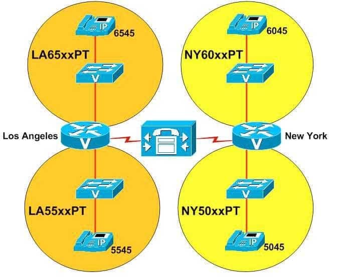
300-835 Part 03 Q13 006 You administer the VoIP network shown in the diagram above.
The IP phone user that has been assigned dn 5545 dials 6045 and receives a busy signal.
Which of the following is most likely the problem?
- The dn 6045 is listed in the <None> search space.
- The IP phone at 5545 is using a device search space.
- The IP phone at 5545 is using a line search space.
- The IP phone at 5545 is using a search space that does not include NY60xxPT.
- The IP phone at 5545 is using a search space that does not include NY50xxPT.
- The IP phone at 5545 is using a search space that does not include LA65xxPT.
- The IP phone at 5545 is using a search space that does not include LA55xxPT.
Explanation:
The problem is most likely that the IP phone at extension 5545 is using a search space that does not include the NY60xxPT partition. A partition is a logical grouping of Voice over IP (VoIP) route patterns and directory numbers (dns). A search space is an ordered list of partitions that a device is allowed to search for patterns that match a dialed number. A device that is not able to match a dialed number in any of the search spaces that are assigned to the device will generate a busy signal. For example, an administrator could segregate local and long distance route patterns into two partitions named LocalPT and LongDistancePT, respectively. The administrator could then assign devices that should not be able to make long distance calls to a search space named Local that includes only the LocalPT partition. Thus devices that have been assigned to only the Local search space could not make long distance calls.In the network shown above, the NY60xxPT partition contains an IP phone that has been assigned the dn 6045. When the user at the IP phone that has been assigned the extension 5545 attempts to dial 6045, the user receives a busy signal. Therefore, it is most likely that the IP phone that has been assigned extension 5545 has not been assigned a search space that includes the NY60xxPT partition.
It is not likely a problem that the IP phone at 5545 is using a device search space. It is also not likely a problem that the IP phone at 5545 is using a line search space. A device search space is a search space that is assigned to a device itself. The information in a device search space will be searched no matter which line on a device is chosen for the outgoing call. A line search space, on the other hand, is a search space that is assigned to a single line on a device, not to the device itself. The information in a line search space will be searched when the user chooses the line to which the search space is assigned as the outgoing line for the call.
If a device is configured with both a device search space and a line search space, the device will combine the two search spaces and search the information that is contained in the line search space first. For example, if you assign the Local search space to a device and the LongDistance search space to a line on the same device, the LongDistance search space will be searched first, even if the user dials a local extension. If the same route pattern or dn exists in both search spaces, the LongDistance search space will be used to break the tie.
It is not likely that dn 6045 is listed in the <None> search space. Any VoIP endpoint can match the route pattern or dn that is contained within the <None> search space because every VoIP endpoint is assigned the <None> search space by default. The <None> search space contains the <None> partition. The <None> partition initially contains all the dns that are configured in the VoIP network. Therefore, you should move dns from the <None> partition to a custom partition to limit specific pattern matching to specific endpoints. The IP phone at 5545 would be able to call the IP phone at 6045 if 6045 were listed in the <None> search space.
It is not likely that the IP phone at 5545 is using a search space that does not include the NY50xxPT partition, does not include the LA55xxPT partition, or does not include the LA65xxPT partition. Nothing in the scenario indicates that the IP phone at 5545 is receiving a busy signal when the user attempts to dial extensions that are included in those partitions.
-
Which of the following interfaces handles the exchange of availability information between UCM and CUPS?
- AXL/SOAP
- LDAP
- SIP
- XMPP
Explanation:
A Session Initiation Protocol (SIP) interface handles the exchange of availability information between Cisco Unified Communications Manager (UCM) and Cisco Unified Presence Server (CUPS). UCM and a CUPS server together are the primary components of a Cisco Presence deployment. A UCM SIP trunk interface must point to the CUPS server in order for availability information to be exchanged between the two systems. CUPS is also capable of sending SIP subscribe messages to UCM over the SIP trunk if UCM is configured as a Presence gateway.The Extensible Messaging and Presence Protocol (XMPP) interface does not handle the exchange of availability information between UCM and CUPS. However, the XMPP interface is used to handle the exchange of availability information between UCM and XMPP clients, such as instant messaging (IM) clients that are developed by third parties.
The Lightweight Directory Access Protocol (LDAP) interface does not handle the exchange of availability information between UCM and CUPS. However, the LDAP interface is used to synchronize user information between UCM and CUPS in order to create a single sign-on (SSO) user experience or to perform contact searches. For example, a Cisco Unified Personal Communicator user can be authenticated to both the CUPS server and UCM by connecting directly to the CUPS server. LDAP is a directory protocol that is used by other servers, such as CUPS, to perform contact lookups. LDAP listens on Transmission Control Protocol (TCP) port 389 unencrypted or on port 636 over Secure Sockets Layer (SSL). Third-party XMPP clients can also use LDAP to search the database and add users as contacts.
The Cisco Administrative Extensible Markup Language (AXL)/Simple Object Access Protocol (SOAP) interface does not handle the exchange of availability information between UCM and CUPS. However, the AXL/SOAP interface is used to handle database synchronization tasks from UCM to the CUPS database. For synchronization to start, the Sync Agent service must be started on the CUPS server.
-
A user wants to adjust the contrast on a Cisco IP Phone 7961.
Which of the following should you instruct the user to do?
- press the help button on the IP phone
- press the services button on the IP phone
- press the settings button on the IP phone
- press the directories button on the IP phone
Explanation:
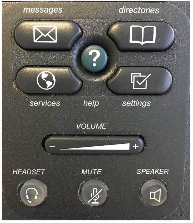
Of the available choices, you should instruct the user to press the settings button on the IP phone in order to enable the user to adjust the contrast on a Cisco IP Phone 7961. The Cisco IP Phone 7961 series includes a bank of buttons with iconography designed to represent the button’s functions. For example, the settings button is represented by a selected check box. The Contrast function is a user preference because it can be adjusted on a per-user basis. Therefore, the user should press settings > User Preferences > Contrast to change the contrast on the IP phone. A typical bank of buttons for a Cisco IP Phone 7961 series appears in the following exhibit:

300-835 Part 03 Q15 007 You should not instruct the user to press the services button. The services button, which is represented by a globe icon, is used to launch IP phone applications. The applications that are available from the services button are dependent on the Cisco Unified Communications deployment and user privilege levels.
You should not instruct the user to press the directories button. The directories button, which is represented by an open book icon, is used to display lists of missed calls, received calls, placed calls, or local directory contacts. If configured, the directories button can also be used to access a custom Personal Speed Dial directory.
You should not instruct the user to press the help button. The help button, which is represented by a question mark (?), is used to provide the end user with information about the specific features of the IP phone. You can press the help button twice while on a call on an IP phone to view statistical information about the call, such as the codec that is being used by the IP phone, the codec that is being used by the calling phone, and packet error information.
-
You want to force new Cisco Unity Connection users to change their TUI passwords when they log in. Which of the following sections should you modify in the user template?
- Name
- Phone
- Location
- Voice Mail Password Settings
- Web Application Password Settings
Explanation:
You should modify the Voice Mail Password Settings section of the Cisco Unity Connection user template to force new users to change their telephone user interface (TUI) passwords when they log in. Cisco Unity Connection users have two passwords: the voice mail system password that is issued by using the telephone keypad and the web application password that is issued by using Cisco Unity Connection’s web-based graphical user interface (GUI). To force new users to change their TUI passwords when they log in, you should click Templates > User Templates in Cisco Unity Connection and then select Voice Mail from the Choose Password dropdown menu. In the Voice Mail Password Settings section, select the User Must Change at Next Sign-In check box and click the Save button.You should not modify the Location section of the user template. The Location section contains fields that enable an administrator to configure geographic information about Cisco Unity Connection users, such as address, language, and time zone settings. If your company has multiple locations in varying time zones, you could create individual user templates for each time zone so that you are not required to modify the time zone each time you add users to a unique location.
You should not modify the Web Application Password Settings section of the user template. The Cisco Unity Connection web-based GUI enables access to the User Web Pages feature of a Cisco Unified Communications environment. The User Web Pages feature can be used to provide users with the ability to perform some customization of their Cisco IP phones or other Unified Communications settings. Because a user enters the web application password by using the GUI, not by using the TUI, you do not need to modify the Web Application Password Settings section in this scenario. To access the Web Application Password Settings section, you should click Templates > User Templates in Cisco Unity Connection and then select Web Application from the Choose Password drop-down menu.
You should not modify the Phone section of the user template. The Phone section enables a Cisco Unity Connection administrator to apply dial plan settings, such as the partition and search space, as well as Class of Service (CoS) settings to users. A partition is a logical grouping of Voice over IP (VoIP) route patterns and directory numbers (dns). A search space is an ordered list of partitions that a device is allowed to search for patterns that match a dialed number. CoS settings enable an administrator to apply a specific set of privileges to Cisco Unity Connection users.
You should not modify the Name section of the user template. The Name section contains the Alias field and the Display Name field, both of which are required fields when creating users in Cisco Unity Connection. An administrator can also configure the way names are displayed by choosing either the First Name, Then Last Name radio button or the Last Name, Then First Name radio button in the Name section.
-
You deploy VoIP on an existing LAN without implementing QoS.
Which of the following issues is least likely to occur as a result?
- jitter
- packet delays
- packet drops
- VoIP hopping
Explanation:
Of the available choices, Voice over IP (VoIP) hopping is least likely to occur as a result of a failure to implement Quality of Service (QoS) on the LAN. VoIP hopping is a form of virtual LAN (VLAN) hopping; it is a data security risk associated with VoIP devices and data devices that are connected to the same physical port on a switch. Many IP phones contain switching technology that enables an administrator to daisy chain a workstation to the phone, causing both the workstation and the IP phone to use the same physical connection to the switch.Jitter, packet delays, and packet drops could all result from deploying VoIP on an existing LAN without implementing QoS. Jitter is a variation in delay, which can cause packets to arrive out of sequence or at a different rate than they were sent. As a result, the end user might experience choppiness in the audio connection. Thus shorter packet roundtrip times contribute to better voice quality. The effects of VoIP issues like jitter and latency on a network can be analyzed by using data analysis techniques such as Mean Opinion Score (MOS) or R-Factor.
Congested networks often cause dropped packets. Dropped packets can cause clips, or breaks, in the audio stream. However, voice traffic is more tolerant of dropped packets than of delayed packets, because a small amount of packet loss is not noticeable to the human ear. Packet loss can be mitigated by implementing QoS and congestion avoidance mechanisms, increasing bandwidth, and increasing buffer space. In addition, some codecs can correct small amounts of packet loss.
Bandwidth is also crucial to the successful deployment of a VoIP network. A lack of bandwidth can lead to issues such as serialization delay. Serialization delay is the time required to place a packet onto a medium, such as a copper or fiber-optic cable. Serialization delay is directly related to the clocking method and the bandwidth of the line.
-
Which of the following cannot be displayed by using the CAR System Reports menu? (Choose two.)
- the current number of billing errors
- the call volume for a given period of time
- malicious call details
- QoS rating information for inbound calls
- Route and Line Group Utilization information
- the top number of users by maximum length of calls
Explanation:
You cannot display Route and Line Group Utilization information by using the Call Detail Records (CDR) Analysis and Reporting (CAR) System Reports menu. In addition, you cannot display the top number of users by maximum length of calls by using the CAR System Reports menu. CAR is a reporting system that can be used to examine a variety of statistics about a Cisco Unified Communications system, including system load and performance.You can display Route and Line Group Utilization information by using the Device Reports menu. The Route and Line Group Utilization report can be accessed by clicking Device Reports > Route Patterns/Hunt Pilots in the Cisco Unified Communications Manager (UCM) CAR graphical user interface (GUI). This report enables a CAR administrator to view Route and Line Group Utilization as a percentage? the report can also be used to determine whether capacity needs to be added to an existing Voice over IP (VoIP) implementation.
You can display information about the top number of users by maximum length of calls by using the User Reports menu. The By Duration report can be accessed by clicking User Reports > Top N in the UCM CAR GUI. This report enables a CAR administrator to view users who have made the longest calls over a given period of time, starting with the user who placed the longest call.
You can display information about the current number of billing errors by using the System Reports > CDR Error report in the UCM CAR GUI. This report enables a CAR administrator to view the number of errors that occurred when CDR data was loaded into the reporting system.
You can display information about call volume for a given period of time by using the System Reports > Traffic > Summary by Phone Number report in the UCM CAR GUI. This report enables a CAR administrator to choose a range of time and IP phone extension numbers from which to view call volume information, thereby enabling an administrator to view what extensions were in use at a specific time.
You can display malicious call details by using the System Reports > Malicious Call Details report in the UCM CAR GUI. This report enables a CAR administrator to view call information that is tracked by the UCM Malicious Call Identification (MCID) service. An administrator can choose to view MCID information over a period of time.
You can display Quality of Service (QoS) rating information for inbound calls by using the System Reports > QoS > Detail report in the UCM CAR GUI. The Detail report enables a CAR administrator to choose a UCM network and a period of time for which to view QoS ratings for both inbound and outbound calls. The Detail report can be used to monitor QoS at a user level.
-
You want to enable a new set of features in Cisco Unified Serviceability.
Which of the following should you do?
- Click Trace > Service Activation.
- Click Alarm > Service Activation.
- Click Tools > Service Activation.
- Click Tools > Serviceability Reports Archive > Service Activation.
Explanation:
You should click Tools > Service Activation in Cisco Unified Serviceability if you want to enable a new set of features. The Service Activation option under the Tools menu enables you to select individual services to activate or select all services at once. After you have selected the services you want to enable, you should click the Save button to activate those services.You should not click Tools > Serviceability Reports Archive > Service Activation, because the Service Activation option is not available under the Serviceability Reports Archive option. However, you can access the Service Statistics Report by navigating to Tools > Serviceability Reports Archive in Cisco Unified Serviceability. The Cisco Unified Serviceability Reports Archive contains all of the following types of statistical reports:
-Device Statistics Report
-Server Statistics Report
-Service Statistics Report
-Call Activities Report
-Alert Summary Report
-Performance Protection ReportYou should not click Alarm > Service Activation, because the Service Activation option is not available under the Alarm menu. The Cisco Unified Serviceability Alarm menu helps identify problems that exist with the Cisco Unified Communications system. The Alarm menu can be used as part of the troubleshooting process.
You should not click Trace > Service Activation, because the Service Activation option is not available under the Trace menu. The Trace menu can be used to access voice application tracing tools that can be used in troubleshooting efforts.
-
You create a new Cisco Unity Connection user based on a custom template that configures the user’s maximum voice mail message length to 500 seconds.
Your supervisor informs you that the voice mail message length limit should be changed to 300 seconds.
You should complete your task by using the least administrative effort.
Which of the following should you do?
- Modify the user template to automatically reconfigure all existing users.
- Modify the user template, and manually reconfigure existing users one by one.
- Modify the user template, and use the BAT to update existing users.
- Modify the user template, and manually reconfigure existing users in Bulk Edit mode.
Explanation:
You should modify the user template and manually reconfigure existing users in Bulk Edit mode to change the voice mail message length limit for the voice mail users to 300 seconds by using the least administrative effort. Modifying the user template to limit voice mail messages to 300 seconds will ensure that any new accounts that are created from that template will automatically be configured with the correct message length limit. In addition, Bulk Edit mode enables an administrator to select a specific subset of Unity Connection users and make identical changes to every user in that subset at once. Therefore, you can use Bulk Edit mode to modify the message length limit for all existing users who have voice mail.Modifying the user template and using the Bulk Administration Tool (BAT) to update existing users will not complete your task by using the least administrative effort. The BAT enables administrators to import users, update user settings, and delete users by importing comma-separated values (CSV) files. The BAT is also capable of exporting users to CSV files. In order to update the message length limit by using the BAT, you would need to export the subset of voice mail users to a CSV file, change the message length limit value for each user in the CSV file, and then import the CSV file again. Exporting, updating, and importing the CSV files would consume more time than applying a single change to a subset of accounts at once by using the Bulk Edit tool.
Modifying the user template alone will not complete your task. If you modify an existing user template, only new user accounts that are based off that template will be affected by the changes that you make to the template. Any users who have already been created from the template will retain the old template settings.
Modifying the user template and manually reconfiguring existing users one by one will not complete your task by using the least administrative effort. If you were to manually reconfigure existing users one by one, you would need to search for the users, open a user, modify the Maximum Message Length field, save the user, and then open the next user in the search results. Having to manually open and modify each user would consume more time than editing the entire subset of users at once.