2.1.2 Lab – Observe STP Topology Changes and Implement RSTP Answers
Lab – Observe STP Topology Changes and Implement RSTP (Answers Version)
Answers Note: Red font color or gray highlights indicate text that appears in the instructor copy only.
Topology
Addressing Table
|
Device |
Interface |
IPv4 Address |
|
D1 |
VLAN1 |
10.0.0.1/8 |
|
D2 |
VLAN1 |
10.0.0.2/8 |
|
A1 |
VLAN1 |
10.0.0.3/8 |
Objectives
Part 1: Build the Network and Configure Basic Device Settings
Part 2: Observe STP Convergence and Topology Change
Part 3: Configure and Verify Rapid Spanning Tree
Background / Scenario
The potential effect of a loop in the Layer 2 network is significant. Layer 2 loops could impact connected hosts as well as the network equipment. Layer 2 loops can be prevented by following good design practices and careful implementation of the Spanning Tree Protocol. In this lab, you will observe the operation of spanning tree protocols to protect the Layer 2 network from loops and topology disruptions. The terms “switch” and “bridge” will be used interchangeably throughout the lab.
Note: This lab is an exercise in deploying and verifying various STP mechanisms. It does not reflect networking best practices.
Note: The switches used with CCNP hands-on labs are Cisco 3650 with Cisco IOS XE release 16.9.4 (universalk9 image) and Cisco 2960+ with IOS release 15.2 (lanbase image). Other routers and Cisco IOS versions can be used. Depending on the model and Cisco IOS version, the commands available and the output produced might vary from what is shown in the labs.
Note: Ensure that the switches have been erased and have no startup configurations. If you are unsure contact your instructor.
Answers Note: Refer to the Answers Lab Manual for the procedures to initialize and reload devices.
Required Resources
- 2 Switches (Cisco 3650 with Cisco IOS XE release 16.9.4 universal image or comparable)
- 1 Switch (Cisco 2960+ with Cisco IOS release 15.2 lanbase image or comparable)
- 1 PC (Windows with a terminal emulation program, such as Tera Term)
- Console cables to configure the Cisco IOS devices via the console ports
- Ethernet cables as shown in the topology
Instructions
Part 1: Build the Network and Configure Basic Device Settings and Interface Addressing
In Part 1, you will set up the network topology and configure basic settings and interface addressing on routers.
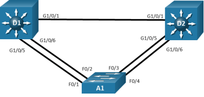
Step 1: Cable the network as shown in the topology.
Attach the devices as shown in the topology diagram, and cable as necessary.
Step 2: Configure basic settings for each switch.
- Console into each switch, enter global configuration mode, and apply the basic settings and interface addressing. The startup configuration is provided below for each switch in the topology.
Open configuration window
Switch D1
hostname D1
spanning-tree mode pvst
banner motd # D1, STP Topology Change and RSTP Lab #
line con 0
exec-timeout 0 0
logging synchronous
exit
interface range g1/0/1-24, g1/1/1-4, g0/0
shutdown
exit
interface range g1/0/1, g1/0/5-6
switchport mode trunk
no shutdown
exit
vlan 2
name SecondVLAN
exit
interface vlan 1
ip address 10.0.0.1 255.0.0.0
no shut
exit
Switch D2
hostname D2
banner motd # D2, STP Topology Change and RSTP Lab #
spanning-tree mode pvst
line con 0
exec-timeout 0 0
logging synchronous
exit
interface range g1/0/1-24, g1/1/1-4, g0/0
shutdown
exit
interface range g1/0/1, g1/0/5-6
switchport mode trunk
no shutdown
exit
vlan 2
name SecondVLAN
exit
interface vlan 1
ip address 10.0.0.2 255.0.0.0
no shut
exit
Switch A1
hostname A1
banner motd # A1, STP Topology Change and RSTP Lab #
spanning-tree mode pvst
line con 0
exec-timeout 0 0
logging synchronous
exit
interface range f0/1-24, g0/1-2
shutdown
exit
interface range f0/1-4
switchport mode trunk
no shutdown
exit
vlan 2
name SecondVLAN
exit
interface vlan 1
ip address 10.0.0.3 255.0.0.0
no shut
exit
- Set the clock on each switch to UTC time.
- Save the running configuration to startup-config.
Close configuration window
Note: Outputs and Spanning Tree topologies highlighted in this lab may be different than what you observe using your own equipment. It is critically important for you to understand how Spanning Tree makes its decisions, and how those decisions impact the operational topology of the network.
Part 2: Discover the Default Spanning Tree
Your switches have been configured and interfaces have been enabled, and the Spanning Tree Protocol, operational by default, has already converged onto a loop-free logical network. In this part of the lab, we will discover what that default spanning tree looks like and evaluate why it converged the way it did. We will do this by following the same set of steps that Spanning Tree does. We will find the Root Bridge, then find the Root Ports, and lastly see which ports are Designated ports, and which ports are non-Designated ports in our topology.
Step 1: Find the root bridge.
Our switches are running the Cisco default PVST+, and we have two VLANs in the network, so we should see two root bridges.
- On A1, issue the command show spanning-tree root and observe what the output tells you about the root bridge. Amongst the lab devices being used to document this lab, A1 shows the root id with a cost of 19 and the root port as interface FastEthernet 0/1 for both VLAN1 and VLAN2.
Open configuration window
A1# show spanning-tree root
Root Hello Max Fwd
Vlan Root ID Cost Time Age Dly Root Port
—————- ——————– ——— —– — — ————
VLAN0001 32769 d8b1.9028.af80 19 2 20 15 Fa0/1
VLAN0002 32770 d8b1.9028.af80 19 2 20 15 Fa0/1
Because we know from the physical topology diagram that A1 is connected to D1 using F0/1, and that interface is a FastEthernet interface, therefore having a cost of 19, D1 is the root bridge for both VLAN 1 and VLAN 2. The question at this point is – why?
- The root bridge is elected based upon which switch has the highest Bridge ID (BID). The BID is made up of a configurable priority value (which defaults to 32768) and the base MAC address for the switch. Use the command show spanning-tree root to gather that information from your switches to support the root bridge decision.
D1# show spanning-tree root
Root Hello Max Fwd
Vlan Root ID Cost Time Age Dly Root Port
—————- ——————– ——— —– — — ————
VLAN0001 32769 d8b1.9028.af80 0 2 20 15
VLAN0002 32770 d8b1.9028.af80 0 2 20 15
D2# show spanning-tree root
Root Hello Max Fwd
Vlan Root ID Cost Time Age Dly Root Port
—————- ——————– ——— —– — — ————
VLAN0001 32769 d8b1.9028.af80 4 2 20 15 Gi1/0/1
VLAN0002 32770 d8b1.9028.af80 4 2 20 15 Gi1/0/1
A1# show spanning-tree root
Root Hello Max Fwd
Vlan Root ID Cost Time Age Dly Root Port
—————- ——————– ——— —– — — ————
VLAN0001 32769 d8b1.9028.af80 19 2 20 15 Fa0/1
VLAN0002 32770 d8b1.9028.af80 19 2 20 15 Fa0/1
The first thing to look at is the priority value. It is 32768 by default. Because we are working with PVST+, a differentiator is added – the priority value is modified with the extended system ID, which is equal to the VLAN number. You can see in the output here that our three devices are using default priorities – 32769 for VLAN 1 (32768 + 1) and 32770 for VLAN 2 (32768 + 2). For each VLAN, the priority values are the same for each of the three switches. When this happens, the rest of the BID is taken into account. The rest of the BID includes the base MAC address. The lowest base MAC address is used to break the tie.
- What are the base MAC addresses for the devices we are using? Issue the command show version | include MAC (capitalized exactly like that) on each switch.
D1# show version | include MAC
Base Ethernet MAC Address : d8:b1:90:28:af:80
D2# show version | include MAC
Base Ethernet MAC Address : d8:b1:90:5d:c3:00
D2#
A1# show version | include MAC
Base ethernet MAC Address : F0:78:16:47:45:80
Amongst the three switches being used to document this lab, D1 has the lowest base MAC address. The OUI portion of each MAC address is the same. The first set of hexadecimal characters are different; 0x28 is a lower number than 0x5d. This is what has caused D1 to be elected as the root bridge.
Close configuration window
Step 2: Find the Root Port for each switch.
Each switch will have one single root port. This port represents the lowest path cost to the root bridge. Path Cost is the total of the Port Costs in the path to the root bridge. The Port Cost is based upon the bandwidth value of the port, and it can either be dynamically assigned or statically configured.
- As we saw in the previous output of show spanning-tree root on each switch, the Path Cost can be different amongst switches. In this case, the path cost from A1 to D1 is 19, reflecting connectivity via a FastEthernet port, while the path cost from D2 to D1 is 4, reflecting connectivity via a GigabitEthernet port.
Open configuration window
D1# show spanning-tree root
Root Hello Max Fwd
Vlan Root ID Cost Time Age Dly Root Port
—————- ——————– ——— —– — — ————
VLAN0001 32769 d8b1.9028.af80 0 2 20 15
VLAN0002 32770 d8b1.9028.af80 0 2 20 15
D2# show spanning-tree root
Root Hello Max Fwd
Vlan Root ID Cost Time Age Dly Root Port
—————- ——————– ——— —– — — ————
VLAN0001 32769 d8b1.9028.af80 4 2 20 15 Gi1/0/1
VLAN0002 32770 d8b1.9028.af80 4 2 20 15 Gi1/0/1
A1# show spanning-tree root
Root Hello Max Fwd
Vlan Root ID Cost Time Age Dly Root Port
—————- ——————– ——— —– — — ————
VLAN0001 32769 d8b1.9028.af80 19 2 20 15 Fa0/1
VLAN0002 32770 d8b1.9028.af80 19 2 20 15 Fa0/1
- These are direct connections to the root, so port cost and path cost are the same. This can be seen in the output of show spanning-tree.
A1# show spanning-tree
VLAN0001
Spanning tree enabled protocol ieee
Root ID Priority 32769
Address d8b1.9028.af80
Cost 19
Port 1 (FastEthernet0/1)
Hello Time 2 sec Max Age 20 sec Forward Delay 15 sec
Bridge ID Priority 32769 (priority 32768 sys-id-ext 1)
Address f078.1647.4580
Hello Time 2 sec Max Age 20 sec Forward Delay 15 sec
Aging Time 300 sec
Interface Role Sts Cost Prio.Nbr Type
——————- —- — ——— ——– ——————————–
Fa0/1 Root FWD 19 128.1 P2p
Fa0/2 Altn BLK 19 128.2 P2p
<some output omitted>
- Our topology does not really illustrate the difference between port cost and path cost very well, so we will introduce a change in the network to achieve this. At D1, shutdown the g1/0/1 interface. The result of this is that D2 will have to change the port it considers root, and we will then see the difference between port cost and path cost.
D1(config)# interface g1/0/1
D1(config-if)# shutdown
- On D2, issue the command show spanning-tree and you will see the port cost and path cost values separating themselves.
D2# show spanning-tree
VLAN0001
Spanning tree enabled protocol ieee
Root ID Priority 32769
Address d8b1.9028.af80
Cost 38
Port 5 (GigabitEthernet1/0/5)
Hello Time 2 sec Max Age 20 sec Forward Delay 15 sec
Bridge ID Priority 32769 (priority 32768 sys-id-ext 1)
Address d8b1.905d.c300
Hello Time 2 sec Max Age 20 sec Forward Delay 15 sec
Aging Time 15 sec
Interface Role Sts Cost Prio.Nbr Type
——————- —- — ——— ——– ——————————–
Gi1/0/5 Root FWD 19 128.5 P2p
Gi1/0/6 Altn BLK 19 128.6 P2p
The root path cost is now 38, while the root port cost is 19. For D2 to reach the root bridge D1, it must traverse two FastEthernet links, and 19 times 2 is 38.
Close configuration window
Step 3: Identify Designated Ports.
The Spanning Tree Designated Port can be traced back to the early versions of the protocol, which were developed when LAN segments were shared, multiaccess networks. In these networks, there was a very real possibility that there could be users attached to a segment between two switches.
The job of the Designated Port back then was to ensure that users had a way to access the network from a given segment, and there was always one Designated Port on each segment. In the switched networks of today, there are very few shared segments, so the job of the Designated Port is more to help maintain the network topology.
A Designated Port stays active in the topology, both sending BPDUs and learning MAC addresses. Every port on the Root Bridge is a Designated Port. Further, there is one Designated Port on every segment that is not attached directly to the root.
Open configuration window
- If you have not already done so, issue the no shutdown command for D1 interface g1/0/1. This will restore our full topology and allow for the non-root attached segment to exist (the links between A1 and D2).
- On D2, issue the show spanning-tree command, and you will see that there are two ports now identified as being in the Designated Port role.
D2# show spanning-tree
VLAN0001
Spanning tree enabled protocol ieee
Root ID Priority 32769
Address d8b1.9028.af80
Cost 4
Port 1 (GigabitEthernet1/0/1)
Hello Time 2 sec Max Age 20 sec Forward Delay 15 sec
Bridge ID Priority 32769 (priority 32768 sys-id-ext 1)
Address d8b1.905d.c300
Hello Time 2 sec Max Age 20 sec Forward Delay 15 sec
Aging Time 300 sec
Interface Role Sts Cost Prio.Nbr Type
——————- —- — ——— ——– ——————————–
Gi1/0/1 Root FWD 4 128.1 P2p
Gi1/0/5 Desg FWD 19 128.5 P2p
Gi1/0/6 Desg FWD 19 128.6 P2p
- And now look at the segments from the A1 side. Issue the show spanning-tree command on A1.
A1# show spanning-tree
VLAN0001
Spanning tree enabled protocol ieee
Root ID Priority 32769
Address d8b1.9028.af80
Cost 19
Port 1 (FastEthernet0/1)
Hello Time 2 sec Max Age 20 sec Forward Delay 15 sec
Bridge ID Priority 32769 (priority 32768 sys-id-ext 1)
Address f078.1647.4580
Hello Time 2 sec Max Age 20 sec Forward Delay 15 sec
Aging Time 300 sec
Interface Role Sts Cost Prio.Nbr Type
——————- —- — ——— ——– ——————————–
Fa0/1 Root FWD 19 128.1 P2p
Fa0/2 Altn BLK 19 128.2 P2p
Fa0/3 Altn BLK 19 128.3 P2p
Fa0/4 Altn BLK 19 128.4 P2p
Interfaces F0/3 and F0/4 on A1 are in the Alternate Role, which is the Cisco PVST+ version of the IEEE 802.1D Discarding role. These interfaces are up and receiving BPDUs from the Designated Ports on each segment, but they will not learn MAC addresses or forward traffic until they stop receiving those BDPUs and move to the Designated state.
Why is D2 controlling the Designated Port role on these two segments? Because from the middle of the segment, D2 has a lower cost to the root bridge than does A1. The root cost on D2 is 4, while the root cost on A1 is 19. Therefore, it takes and maintains the Designated Ports for these two segments.
- You may have noticed in the previous output that the two links from A1 to D1 were not being used.
Fa0/1 Root FWD 19 128.1 P2p
Fa0/2 Altn BLK 19 128.2 P2p
Each switch can only have a single root port. In this example, F0/2, which is in the Alternate Role, would only take over if F0/1 were to fail. The decision about which interface to use in this scenario is based on the lowest port priority, which defaults to 128.interface_id.
Close configuration window
Part 3: Implement and Observe Rapid Spanning Tree Protocol
In Part 3, you will implement Rapid Spanning Tree Protocol (RSTP) on all the switches. Using the same basic rules, RSTP speeds up convergence significantly.
- On D2, issue the debug spanning-tree events command, and then issue the shutdown command for interface g1/0/1 and observe the output.
Open configuration window
D2# debug spanning-tree events
D2# config t
D2(config)# interface g1/0/1
D2(config-if)# shutdown
D2(config-if)#
*Dec 24 13:07:10.790: %LINK-5-CHANGED: Interface GigabitEthernet1/0/1, changed state to administratively down
*Dec 24 13:07:11.790: %LINEPROTO-5-UPDOWN: Line protocol on Interface GigabitEthernet1/0/1, changed state to down
D2(config-if)#
*Dec 24 13:07:28.159: STP: VLAN0001 heard root 32769-d8b1.9028.af80 on Gi1/0/5
*Dec 24 13:07:28.160: supersedes 32769-d8b1.905d.c300
*Dec 24 13:07:28.161: STP: VLAN0001 new root is 32769, d8b1.9028.af80 on port Gi1/0/5, cost 38
*Dec 24 13:07:28.162: STP: VLAN0001 sent Topology Change Notice on Gi1/0/5
*Dec 24 13:07:28.165: STP[1]: Generating TC trap for port GigabitEthernet1/0/6
*Dec 24 13:07:28.166: STP: VLAN0001 Gi1/0/6 -> blocking
*Dec 24 13:07:28.166: STP: VLAN0002 heard root 32770-d8b1.9028.af80 on Gi1/0/5
*Dec 24 13:07:28.167: supersedes 32770-d8b1.905d.c300
*Dec 24 13:07:28.167: STP: VLAN0002 new root is 32770, d8b1.9028.af80 on port Gi1/0/5, cost 38
D2(config-if)#
*Dec 24 13:07:28.169: STP: VLAN0002 sent Topology Change Notice on Gi1/0/5
*Dec 24 13:07:28.171: STP[2]: Generating TC trap for port GigabitEthernet1/0/6
*Dec 24 13:07:28.171: STP: VLAN0002 Gi1/0/6 -> blocking
D2(config-if)#
From the above output, you can see that it took a total of about 17 seconds for spanning tree to adjust to the topology change. Rapid Spanning Tree can adjust much faster.
- On D1, change the spanning tree mode to rapid-pvst:
D1(config)# spanning-tree mode rapid-pvst
D1(config)#
*Dec 24 13:14:48.458: %LINK-3-UPDOWN: Interface Vlan1, changed state to down
*Dec 24 13:14:49.459: %LINEPROTO-5-UPDOWN: Line protocol on Interface Vlan1, changed state to down
D1(config)#
*Dec 24 13:15:18.452: %LINK-3-UPDOWN: Interface Vlan1, changed state to up
*Dec 24 13:15:19.453: %LINEPROTO-5-UPDOWN: Line protocol on Interface Vlan1, changed state to up
D1(config)#
From the above output, you can see that it took more than 30 seconds for interface VLAN1 to come back up. There are two conditions that must be met for an SVI to be operational. First, the VLAN the SVI is associated with must exist, and second, the VLAN the SVI is associated with must be in spanning tree forwarding mode on at least one interface. It took 30 seconds to adjust. What happened to “rapid”?
- On D1, issue the command show spanning-tree.
D1# show spanning-tree
VLAN0001
Spanning tree enabled protocol rstp
Root ID Priority 32769
Address d8b1.9028.af80
This bridge is the root
Hello Time 2 sec Max Age 20 sec Forward Delay 15 sec
Bridge ID Priority 32769 (priority 32768 sys-id-ext 1)
Address d8b1.9028.af80
Hello Time 2 sec Max Age 20 sec Forward Delay 15 sec
Aging Time 300 sec
Interface Role Sts Cost Prio.Nbr Type
——————- —- — ——— ——– ——————————–
Gi1/0/5 Desg FWD 19 128.5 P2p Peer(STP)
Gi1/0/6 Desg FWD 19 128.6 P2p Peer(STP)
The type values tell the story. Rapid spanning tree is backwards compatible with common spanning tree. It achieves this backwards compatibility by falling back to using the timers and settings of common spanning tree. In other words, we will not see the benefits of rapid spanning tree if only one switch is running it.
- On D2 and A1, change the spanning tree mode to rapid spanning tree.
A1(config)# spanning-tree mode rapid-pvst
A1(config)#
Dec 24 13:31:51.023: %LINEPROTO-5-UPDOWN: Line protocol on Interface Vlan1, changed state to down
Dec 24 13:31:51.081: %LINEPROTO-5-UPDOWN: Line protocol on Interface Vlan1, changed state to up
A1(config)#
A1 was the last switch that was configured for RSTP. As you can see, interface VLAN1 was only down for 0.048 seconds. This is the “rapid” in rapid spanning tree.
Open configuration window
End of document
Device Configs – Final
Switch D1
D1# show run
Building configuration…
Current configuration : 8871 bytes
!
version 16.9
no service pad
service timestamps debug datetime msec
service timestamps log datetime msec
! Call-home is enabled by Smart-Licensing.
service call-home
no platform punt-keepalive disable-kernel-core
!
hostname D1
!
vrf definition Mgmt-vrf
!
address-family ipv4
exit-address-family
!
address-family ipv6
exit-address-family
!
no aaa new-model
switch 1 provision ws-c3650-24ts
!
login on-success log
!
license boot level ipservicesk9
!
diagnostic bootup level minimal
!
spanning-tree mode rapid-pvst
spanning-tree extend system-id
!
redundancy
mode sso
!
transceiver type all
monitoring
!
class-map match-any system-cpp-police-topology-control
description Topology control
class-map match-any system-cpp-police-sw-forward
description Sw forwarding, L2 LVX data, LOGGING
class-map match-any system-cpp-default
description Inter FED, EWLC control, EWLC data
class-map match-any system-cpp-police-sys-data
description Learning cache ovfl, High Rate App, Exception, EGR Exception, NFL SAMPLED DATA, RPF Failed
class-map match-any system-cpp-police-punt-webauth
description Punt Webauth
class-map match-any system-cpp-police-l2lvx-control
description L2 LVX control packets
class-map match-any system-cpp-police-forus
description Forus Address resolution and Forus traffic
class-map match-any system-cpp-police-multicast-end-station
description MCAST END STATION
class-map match-any system-cpp-police-multicast
description Transit Traffic and MCAST Data
class-map match-any system-cpp-police-l2-control
description L2 control
class-map match-any system-cpp-police-dot1x-auth
description DOT1X Auth
class-map match-any system-cpp-police-data
description ICMP redirect, ICMP_GEN and BROADCAST
class-map match-any system-cpp-police-stackwise–virt-control
description Stackwise Virtual
class-map match-any non-client-nrt-class
class-map match-any system-cpp-police-routing-control
description Routing control and Low Latency
class-map match-any system-cpp-police-protocol-snooping
description Protocol snooping
class-map match-any system-cpp-police-dhcp-snooping
description DHCP snooping
class-map match-any system-cpp-police-system-critical
description System Critical and Gold Pkt
!
policy-map system-cpp-policy
!
interface GigabitEthernet0/0
vrf forwarding Mgmt-vrf
no ip address
shutdown
negotiation auto
!
interface GigabitEthernet1/0/1
switchport mode trunk
!
interface GigabitEthernet1/0/2
shutdown
!
interface GigabitEthernet1/0/3
shutdown
!
interface GigabitEthernet1/0/4
shutdown
!
interface GigabitEthernet1/0/5
switchport mode trunk
!
interface GigabitEthernet1/0/6
switchport mode trunk
!
interface GigabitEthernet1/0/7
shutdown
!
interface GigabitEthernet1/0/8
shutdown
!
interface GigabitEthernet1/0/9
shutdown
!
interface GigabitEthernet1/0/10
shutdown
!
interface GigabitEthernet1/0/11
shutdown
!
interface GigabitEthernet1/0/12
shutdown
!
interface GigabitEthernet1/0/13
shutdown
!
interface GigabitEthernet1/0/14
shutdown
!
interface GigabitEthernet1/0/15
shutdown
!
interface GigabitEthernet1/0/16
shutdown
!
interface GigabitEthernet1/0/17
shutdown
!
interface GigabitEthernet1/0/18
shutdown
!
interface GigabitEthernet1/0/19
shutdown
!
interface GigabitEthernet1/0/20
shutdown
!
interface GigabitEthernet1/0/21
shutdown
!
interface GigabitEthernet1/0/22
shutdown
!
interface GigabitEthernet1/0/23
shutdown
!
interface GigabitEthernet1/0/24
shutdown
!
interface GigabitEthernet1/1/1
shutdown
!
interface GigabitEthernet1/1/2
shutdown
!
interface GigabitEthernet1/1/3
shutdown
!
interface GigabitEthernet1/1/4
shutdown
!
interface Vlan1
ip address 10.0.0.1 255.0.0.0
!
ip forward-protocol nd
ip http server
ip http authentication local
ip http secure-server
!
control-plane
service-policy input system-cpp-policy
!
banner motd ^C D1, STP Topology Change and RSTP Lab ^C
!
line con 0
exec-timeout 0 0
logging synchronous
stopbits 1
line aux 0
stopbits 1
line vty 0 15
!
end
Switch D2
D2# show run
Building configuration…
Current configuration : 8881 bytes
!
version 16.9
no service pad
service timestamps debug datetime msec
service timestamps log datetime msec
! Call-home is enabled by Smart-Licensing.
service call-home
no platform punt-keepalive disable-kernel-core
!
hostname D2
!
vrf definition Mgmt-vrf
!
address-family ipv4
exit-address-family
!
address-family ipv6
exit-address-family
!
no aaa new-model
switch 1 provision ws-c3650-24ts
!
login on-success log
!
license boot level ipservicesk9
!
diagnostic bootup level minimal
!
spanning-tree mode rapid-pvst
spanning-tree extend system-id
!
redundancy
mode sso
!
transceiver type all
monitoring
!
class-map match-any system-cpp-police-topology-control
description Topology control
class-map match-any system-cpp-police-sw-forward
description Sw forwarding, L2 LVX data, LOGGING
class-map match-any system-cpp-default
description Inter FED, EWLC control, EWLC data
class-map match-any system-cpp-police-sys-data
description Learning cache ovfl, High Rate App, Exception, EGR Exception, NFL SAMPLED DATA, RPF Failed
class-map match-any system-cpp-police-punt-webauth
description Punt Webauth
class-map match-any system-cpp-police-l2lvx-control
description L2 LVX control packets
class-map match-any system-cpp-police-forus
description Forus Address resolution and Forus traffic
class-map match-any system-cpp-police-multicast-end-station
description MCAST END STATION
class-map match-any system-cpp-police-multicast
description Transit Traffic and MCAST Data
class-map match-any system-cpp-police-l2-control
description L2 control
class-map match-any system-cpp-police-dot1x-auth
description DOT1X Auth
class-map match-any system-cpp-police-data
description ICMP redirect, ICMP_GEN and BROADCAST
class-map match-any system-cpp-police-stackwise–virt-control
description Stackwise Virtual
class-map match-any non-client-nrt-class
class-map match-any system-cpp-police-routing-control
description Routing control and Low Latency
class-map match-any system-cpp-police-protocol-snooping
description Protocol snooping
class-map match-any system-cpp-police-dhcp-snooping
description DHCP snooping
class-map match-any system-cpp-police-system-critical
description System Critical and Gold Pkt
!
policy-map system-cpp-policy
!
!
interface GigabitEthernet0/0
vrf forwarding Mgmt-vrf
no ip address
shutdown
negotiation auto
!
interface GigabitEthernet1/0/1
switchport mode trunk
shutdown
!
interface GigabitEthernet1/0/2
shutdown
!
interface GigabitEthernet1/0/3
shutdown
!
interface GigabitEthernet1/0/4
shutdown
!
interface GigabitEthernet1/0/5
switchport mode trunk
!
interface GigabitEthernet1/0/6
switchport mode trunk
!
interface GigabitEthernet1/0/7
shutdown
!
interface GigabitEthernet1/0/8
shutdown
!
interface GigabitEthernet1/0/9
shutdown
!
interface GigabitEthernet1/0/10
shutdown
!
interface GigabitEthernet1/0/11
shutdown
!
interface GigabitEthernet1/0/12
shutdown
!
interface GigabitEthernet1/0/13
shutdown
!
interface GigabitEthernet1/0/14
shutdown
!
interface GigabitEthernet1/0/15
shutdown
!
interface GigabitEthernet1/0/16
shutdown
!
interface GigabitEthernet1/0/17
shutdown
!
interface GigabitEthernet1/0/18
shutdown
!
interface GigabitEthernet1/0/19
shutdown
!
interface GigabitEthernet1/0/20
shutdown
!
interface GigabitEthernet1/0/21
shutdown
!
interface GigabitEthernet1/0/22
shutdown
!
interface GigabitEthernet1/0/23
shutdown
!
interface GigabitEthernet1/0/24
shutdown
!
interface GigabitEthernet1/1/1
shutdown
!
interface GigabitEthernet1/1/2
shutdown
!
interface GigabitEthernet1/1/3
shutdown
!
interface GigabitEthernet1/1/4
shutdown
!
interface Vlan1
ip address 10.0.0.2 255.0.0.0
!
ip forward-protocol nd
ip http server
ip http authentication local
ip http secure-server
!
control-plane
service-policy input system-cpp-policy
!
banner motd ^C D2, STP Toplogy Change and RSTP Lab ^C
!
line con 0
exec-timeout 0 0
logging synchronous
stopbits 1
line aux 0
stopbits 1
line vty 0 15
!
end
Switch A1
A1# show run
Building configuration…
Current configuration : 2008 bytes
!
version 15.2
no service pad
service timestamps debug datetime msec
service timestamps log datetime msec
no service password-encryption
!
hostname A1
!
boot-start-marker
boot-end-marker
!
no aaa new-model
system mtu routing 1500
!
spanning-tree mode rapid-pvst
spanning-tree extend system-id
!
vlan internal allocation policy ascending
!
interface FastEthernet0/1
switchport mode trunk
!
interface FastEthernet0/2
switchport mode trunk
!
interface FastEthernet0/3
switchport mode trunk
!
interface FastEthernet0/4
switchport mode trunk
!
interface FastEthernet0/5
shutdown
!
interface FastEthernet0/6
shutdown
!
interface FastEthernet0/7
shutdown
!
interface FastEthernet0/8
shutdown
!
interface FastEthernet0/9
shutdown
!
interface FastEthernet0/10
shutdown
!
interface FastEthernet0/11
shutdown
!
interface FastEthernet0/12
shutdown
!
interface FastEthernet0/13
shutdown
!
interface FastEthernet0/14
shutdown
!
interface FastEthernet0/15
shutdown
!
interface FastEthernet0/16
shutdown
!
interface FastEthernet0/17
shutdown
!
interface FastEthernet0/18
shutdown
!
interface FastEthernet0/19
shutdown
!
interface FastEthernet0/20
shutdown
!
interface FastEthernet0/21
shutdown
!
interface FastEthernet0/22
shutdown
!
interface FastEthernet0/23
shutdown
!
interface FastEthernet0/24
shutdown
!
interface GigabitEthernet0/1
shutdown
!
interface GigabitEthernet0/2
shutdown
!
interface Vlan1
ip address 10.0.0.3 255.0.0.0
!
ip http server
ip http secure-server
!
banner motd ^C A1, STP Toplogy Change and RSTP Lab ^C
!
line con 0
exec-timeout 0 0
logging synchronous
line vty 0 4
login
line vty 5 15
login
!
end