7.1.3 Lab – OSPFv2 Route Summarization and Filtering Answers
Lab – OSPFv2 Route Summarization and Filtering (Answers Version)
Answers Note: Red font color or gray highlights indicate text that appears in the instructor copy only.
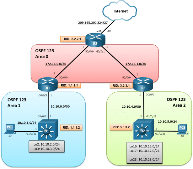
Topology
Addressing Table
|
Device |
Interface |
IPv4 Address |
|
R1 |
G0/0/0 |
172.16.0.2/30 |
|
R1 |
G0/0/1 |
10.10.0.1/30 |
|
R1 |
Lo0 |
209.165.200.225/27 |
|
R2 |
G0/0/0 |
172.16.0.1/30 |
|
R2 |
G0/0/1 |
172.16.1.1/30 |
|
R3 |
G0/0/0 |
172.16.1.2/30 |
|
R3 |
G0/0/1 |
10.10.4.1/30 |
|
D1 |
G1/0/11 |
10.10.0.2/30 |
|
D1 |
G1/0/23 |
10.10.1.1/24 |
|
D1 |
Lo2 |
10.10.2.1/24 |
|
D1 |
Lo3 |
10.10.3.1/24 |
|
D2 |
G1/0/11 |
10.10.4.2/30 |
|
D2 |
G1/0/23 |
10.10.5.1/24 |
|
D2 |
Lo16 |
10.10.16.1/24 |
|
D2 |
Lo17 |
10.10.17.1/24 |
|
D2 |
Lo18 |
10.10.18.1/24 |
|
D2 |
Lo19 |
10.10.19.1/24 |
|
D2 |
Lo20 |
10.10.20.1/24 |
|
D2 |
Lo21 |
10.10.21.1/24 |
|
D2 |
Lo22 |
10.10.22.1/24 |
|
D2 |
Lo23 |
10.10.23.1/24 |
|
PC1 |
NIC |
10.10.1.10/24 |
|
PC2 |
NIC |
10.10.5.10/24 |
Objectives
Part 1: Build the Network, Configure Basic Device Settings and Routing
Part 2: OSPFv2 Route Summarization
Part 3: OSPFv2 Route Filtering
Background / Scenario
Areas make OSPF more scalable and increase efficiency. Consider a large multinational organization with a thousand OSPF routers. If all routers were in a single area, the information contained in their LSDB would be overwhelming. Segmenting the OSPF domain into multiple areas reduces the size of the LSDB for each area, making SPF tree calculations faster, and decreasing LSDB flooding between routers when a link flaps.
To make OSPF even more scalable and efficient, network routes can be summarized and advertised in other areas. As well, specific route filtering can be used to provide more precise control on route propagation.
In this lab, you will configure route summarization and route filtering in a multiarea OSPF version 2 network. This lab was specifically designed to use three routers and two Layer 3 switches. To help visualize the potential of summarization and route filtering, additional loopback interfaces will be configured to simulate LANs and create larger routing tables.
Note: This lab is an exercise in developing, deploying, and verifying how OSPF route summarization and filtering operates and does not reflect networking best practices.
Note: The router used with this CCNP hands-on lab is a Cisco 4221and the two Layer 3 switches are Catalyst 3560 switches. Other routers and Layer 3 switches and Cisco IOS versions can be used. Depending on the model and Cisco IOS version, the commands available and the output produced might vary from what is shown in the labs.
Note: Ensure that the routers and switches have been erased and have no startup configurations. If you are unsure contact your instructor.
Answers Note: Refer to the Answers Lab Manual for the procedures to initialize and reload devices.
Required Resources
- 3 Routers (Cisco 4221 with Cisco IOS XE Release 16.9.4 universal image or comparable)
- 2 Switches (Cisco 3650 with Cisco IOS XE Release 16.9.4 universal image or comparable)
- 2 PCs (Windows with terminal emulation program, such as Tera Term)
- Console cables to configure the Cisco IOS devices via the console ports
- Ethernet cables as shown in the topology
Instructions
Part 1:Build the Network, Configure Basic Device Settings and Routing
In Part 1, you will set up the network topology and configure basic settings and interface addressing on the router and Layer 3 switches. You will also configure multiarea OSPFv2 on the OSPF backbone routers R1, R2, and R3. You will manually configure OSPFv2 on D1 and D2.
Step 1:Cable the network as shown in the topology.
Attach the devices as shown in the topology diagram, and cable as necessary.
Step 2:Configure basic settings for the routers.
- Console into each router, enter global configuration mode, and apply the basic settings, interface addressing, and OSPFv2 configuration. The configuration for each device is provided for you below.
Note: Routers were configured with OSPFv2.
Open configuration window
Router R1
hostname R1
no ip domain lookup
line con 0
logging sync
exec-time 0 0
exit
banner motd # This is R1, OSPFv2 Route Summarization and Filtering Lab #
interface g0/0/0
ip add 172.16.0.2 255.255.255.252
no shut
exit
interface GigabitEthernet0/0/1
ip address 10.10.0.1 255.255.255.252
no shut
exit
router ospf 123
router-id 1.1.1.1
auto-cost reference-bandwidth 1000
network 10.10.0.0 0.0.0.3 area 1
network 172.16.0.0 0.0.0.3 area 0
exit
Router R2
hostname R2
no ip domain lookup
line con 0
logging sync
exec-time 0 0
exit
banner motd # This is R2, OSPFv2 Route Summarization and Filtering Lab #
interface g0/0/0
ip add 172.16.0.1 255.255.255.252
no shut
exit
interface GigabitEthernet0/0/1
ip address 172.16.1.1 255.255.255.252
no shut
exit
int lo0
ip add 209.165.200.225 255.255.255.224
exit
ip route 0.0.0.0 0.0.0.0 Loopback0
router ospf 123
router-id 2.2.2.1
auto-cost reference-bandwidth 1000
network 172.16.0.0 0.0.0.3 area 0
network 172.16.1.0 0.0.0.3 area 0
default-information originate
exit
Router R3
hostname R3
no ip domain lookup
line con 0
logging sync
exec-time 0 0
exit
banner motd # This is R3, OSPFv2 Route Summarization and Filtering Lab #
interface g0/0/0
ip add 172.16.1.2 255.255.255.252
no shut
exit
interface GigabitEthernet0/0/1
ip address 10.10.4.1 255.255.255.252
no shut
exit
router ospf 123
router-id 3.3.3.1
auto-cost reference-bandwidth 1000
network 10.10.4.0 0.0.0.3 area 2
network 172.16.1.0 0.0.0.3 area 0
exit
- Save the running configuration to startup-config.
Close configuration window
Step 3:Configure basic settings for the switches.
- Console into the switch, enter global configuration mode, and apply the basic settings and interface addressing. A command list for each switch is provided below.
Note: OSPF routing will be manually configured.
Open configuration window
Switch D1
hostname D1
no ip domain lookup
line con 0
exec-timeout 0 0
logging synchronous
exit
banner motd # This is D1, OSPFv2 Route Summarization and Filtering Lab #
interface g1/0/11
no switchport
ip address 10.10.0.2 255.255.255.252
no shut
exit
interface g1/0/23
no switchport
ip address 10.10.1.1 255.255.255.0
no shut
exit
int Lo2
ip add 10.10.2.1 255.255.255.0
ip ospf network point-to-point
exit
int Lo3
ip add 10.10.3.1 255.255.255.0
ip ospf network point-to-point
exit
Switch D2
hostname D2
no ip domain lookup
line con 0
logging sync
exec-time 0 0
exit
banner motd # This is D2, OSPFv2 Route Summarization and Filtering Lab #
interface g1/0/11
no switchport
ip address 10.10.4.2 255.255.255.252
no shut
exit
interface g1/0/23
no switchport
ip address 10.10.5.1 255.255.255.0
no shut
exit
int Lo16
ip add 10.10.16.1 255.255.255.0
ip ospf network point-to-point
exit
int Lo17
ip add 10.10.17.1 255.255.255.0
ip ospf network point-to-point
exit
int Lo18
ip add 10.10.18.1 255.255.255.0
ip ospf network point-to-point
exit
int Lo19
ip add 10.10.19.1 255.255.255.0
ip ospf network point-to-point
exit
int Lo20
ip add 10.10.20.1 255.255.255.0
ip ospf network point-to-point
exit
int Lo21
ip add 10.10.21.1 255.255.255.0
ip ospf network point-to-point
exit
int Lo22
ip add 10.10.22.1 255.255.255.0
ip ospf network point-to-point
exit
int Lo23
ip add 10.10.23.1 255.255.255.0
ip ospf network point-to-point
exit
- Save the running configuration to startup-config.
- Verify the interfaces configured on D1.
D1# show ip interface brief | include manual
GigabitEthernet1/0/1110.10.0.2YES manual upup
GigabitEthernet1/0/2310.10.1.1YES manual upup
Loopback210.10.2.1YES manual upup
Loopback310.10.3.1YES manual upup
Notice the loopback interfaces configured on D1. Theses interfaces were configured for lab purposes to simulate other LANs.
Note: Loopback interfaces were numbered based on the network address (e.g., Lo2 = 10.10.2.0/24) for convenience only.
- Verify the interfaces configured on D2.
D2# show ip interface brief | include manual
GigabitEthernet1/0/1110.10.4.2YES manual upup
GigabitEthernet1/0/2310.10.5.1YES manual upup
Loopback1610.10.16.1YES manual upup
Loopback1710.10.17.1YES manual upup
Loopback1810.10.18.1YES manual upup
Loopback1910.10.19.1YES manual upup
Loopback2010.10.20.1YES manual upup
Loopback2110.10.21.1YES manual upup
Loopback2210.10.22.1YES manual upup
Loopback2310.10.23.1YES manual upup
Again, notice the loopback interfaces configured on D1. Theses interfaces were configured for lab purposes to simulate other LANs.
Close configuration window
Step 4:Verify routing on R1, R2, and R3.
- Verify the routing table of R1 using the show ip route ospf command.
Open configuration window
R1# show ip route ospf | begin Gateway
Gateway of last resort is 172.16.0.1 to network 0.0.0.0
O*E20.0.0.0/0 [110/1] via 172.16.0.1, 00:22:17, GigabitEthernet0/0/0
10.0.0.0/8 is variably subnetted, 3 subnets, 2 masks
O IA10.10.4.0/30 [110/3] via 172.16.0.1, 00:21:43, GigabitEthernet0/0/0
172.16.0.0/16 is variably subnetted, 3 subnets, 2 masks
O172.16.1.0/30 [110/2] via 172.16.0.1, 00:22:11, GigabitEthernet0/0/0
The R1 routing table contains an OSPF internal or intra–area route, and interarea route, and an external route to the default gateway.
- Verify the routing table of R2 using the show ip route ospf command.
R2# show ip route ospf | begin Gateway
Gateway of last resort is 0.0.0.0 to network 0.0.0.0
10.0.0.0/30 is subnetted, 2 subnets
O IA10.10.0.0 [110/2] via 172.16.0.2, 00:19:40, GigabitEthernet0/0/0
O IA10.10.4.0 [110/2] via 172.16.1.2, 00:19:07, GigabitEthernet0/0/1
R2 is propagating the static default route and therefore does not have an external type 2 OSPF route (i.e., O* E2) in the routing table like R1 and R3.
- Verify the routing table of R3 using the show ip route ospf command.
R3# show ip route ospf | begin Gateway
Gateway of last resort is 172.16.1.1 to network 0.0.0.0
O*E20.0.0.0/0 [110/1] via 172.16.1.1, 00:20:00, GigabitEthernet0/0/0
10.0.0.0/8 is variably subnetted, 3 subnets, 2 masks
O IA10.10.0.0/30 [110/3] via 172.16.1.1, 00:20:00, GigabitEthernet0/0/0
172.16.0.0/16 is variably subnetted, 3 subnets, 2 masks
O172.16.0.0/30 [110/2] via 172.16.1.1, 00:20:00, GigabitEthernet0/0/0
Like R1, R3 has an internal route (LSA 2), an interarea route (LSA 3), and an external route (LSA 5).
The LANs connected to D1 and D2 are not yet advertised.
Close configuration window
Step 5:Enable OSPFv2 on D1.
- On D1, enable IP routing using the ip routing global configuration command.
Open configuration window
D1(config)# ip routing
- Next, enter the OSPF router configuration mode using process ID 123, assign D1 the router ID 1.1.1.2 and set the reference bandwidth to distinguish between Gigabit Ethernet and FastEthernet interfaces.
D1(config)# router ospf 123
D1(config-router)# router-id 1.1.1.2
D1(config-router)# auto-cost reference-bandwidth 1000
% OSPF: Reference bandwidth is changed.
Please ensure reference bandwidth is consistent across all routers.
Note: Setting the reference cost value too high may cause issues with low-bandwidth interfaces.
- Next, we need to have D1 advertise all four of its directly connected interfaces. Although this could be accomplished using four separate network statements, we will use the wildcard mask to advertise all four interfaces using one network statement.
D1(config-router)# network 10.10.0.0 0.0.3.255 area 1
D1(config-router)# end
*Mar1 01:01:22.540: %OSPF-5-ADJCHG: Process 123, Nbr 1.1.1.1 on GigabitEthernet1/0/11 from LOADING to FULL, Loading Done
- Verify the OSPF routing table on D1.
D1# show ip route ospf | begin Gateway
Gateway of last resort is 10.10.0.1 to network 0.0.0.0
O*E20.0.0.0/0 [110/1] via 10.10.0.1, 00:05:20, GigabitEthernet1/0/11
10.0.0.0/8 is variably subnetted, 9 subnets, 3 masks
O IA10.10.4.0/30 [110/4] via 10.10.0.1, 00:05:20, GigabitEthernet1/0/11
172.16.0.0/30 is subnetted, 2 subnets
O IA172.16.0.0 [110/2] via 10.10.0.1, 00:05:20, GigabitEthernet1/0/11
O IA172.16.1.0 [110/3] via 10.10.0.1, 00:05:20, GigabitEthernet1/0/11
- Verify the routing table of R2 using the show ip route ospf command.
R2# show ip route ospf | begin Gateway
Gateway of last resort is 0.0.0.0 to network 0.0.0.0
10.0.0.0/8 is variably subnetted, 5 subnets, 2 masks
O IA10.10.0.0/30 [110/2] via 172.16.0.2, 00:40:29, GigabitEthernet0/0/0
O IA10.10.1.0/24 [110/12] via 172.16.0.2, 00:06:56, GigabitEthernet0/0/0
O IA10.10.2.0/24 [110/3] via 172.16.0.2, 00:06:56, GigabitEthernet0/0/0
O IA10.10.3.0/24 [110/3] via 172.16.0.2, 00:06:56, GigabitEthernet0/0/0
O IA10.10.4.0/30 [110/2] via 172.16.1.2, 00:39:56, GigabitEthernet0/0/1
Notice how its routing table now includes routes to the D1 LANs. Notice also how this has increased the number of routing entries.
Close configuration window
Step 6:Enable OSPFv2 on D2.
- On D2, enable IP routing using the ip routing global configuration command.
Open configuration window
D2(config)# ip routing
- Next, enter the OSPF router configuration mode using process ID 123, assign D2 the router ID 3.3.3.2 and set the reference bandwidth to distinguish between Gigabit Ethernet and FastEthernet interfaces.
D2(config)# router ospf 123
D2(config-router)# router-id 3.3.3.2
D2(config-router)# auto-cost reference-bandwidth 1000
% OSPF: Reference bandwidth is changed.
Please ensure reference bandwidth is consistent across all routers.
Note: Setting the reference cost value too high may cause issues with low-bandwidth interfaces.
- Advertise the 10.10.4.0/30 and 10.10.5.0 /255 networks. Again, this could be accomplished using separate network statements. However, the wildcard mask can be used to advertise both interfaces using one network statement as shown.
D2(config-router)# network 10.10.4.0 0.0.1.255 area 2
D2(config-router)#
*Mar1 01:15:02.643: %OSPF-5-ADJCHG: Process 123, Nbr 3.3.3.1 on GigabitEthernet1/0/11 from LOADING to FULL, Loading Done
Note: The wildcard mask 0.0.1.255 matches both networks 10.10.4.0/30 and 10.10.5.0/24
- Next, advertise the 10.10.16.0/24 through to 10.10.23.0/24 loopback interface networks. Traditionally, this would require 8 network statements. But again, the wildcard mask can be used to advertise all 8 interfaces using one network statement as shown.
D2(config-router)# network 10.10.16.0 0.0.7.255 area 2
D2(config-router)# end
Note: The wildcard mask 0.0.7.255 matches networks 10.10.16.0/24 through to 10.10.23.0/24.
Close configuration window
Step 7:Verify Routing.
- Verify the routing table of D2 using the show ip route ospf command.
Open configuration window
D2# show ip route ospf | begin Gateway
Gateway of last resort is 10.10.4.1 to network 0.0.0.0
O*E20.0.0.0/0 [110/1] via 10.10.4.1, 00:02:19, GigabitEthernet1/0/11
10.0.0.0/8 is variably subnetted, 24 subnets, 3 masks
O IA10.10.0.0/30 [110/4] via 10.10.4.1, 00:02:19, GigabitEthernet1/0/11
O IA10.10.1.0/24 [110/14] via 10.10.4.1, 00:02:19, GigabitEthernet1/0/11
O IA10.10.2.0/24 [110/5] via 10.10.4.1, 00:02:19, GigabitEthernet1/0/11
O IA10.10.3.0/24 [110/5] via 10.10.4.1, 00:02:19, GigabitEthernet1/0/11
172.16.0.0/30 is subnetted, 2 subnets
O IA172.16.0.0 [110/3] via 10.10.4.1, 00:02:19, GigabitEthernet1/0/11
O IA172.16.1.0 [110/2] via 10.10.4.1, 00:02:19, GigabitEthernet1/0/11
D2 has OSPF route entries for:
- One external OSPF route to the gateway of last resort.
- The four D1 LANs (i.e., 10.10.0.0/30 through 10.10.3.0/24)
- The two Area 0 networks (i.e., 172.16.0.0/30 and 172.16.1.0/30)
- From R2, verify the routing table using the show ip route ospf command.
R2# show ip route ospf | begin Gateway
Gateway of last resort is 0.0.0.0 to network 0.0.0.0
10.0.0.0/8 is variably subnetted, 14 subnets, 2 masks
O IA10.10.0.0/30 [110/2] via 172.16.0.2, 01:00:10, GigabitEthernet0/0/0
O IA10.10.1.0/24 [110/12] via 172.16.0.2, 00:26:37, GigabitEthernet0/0/0
O IA10.10.2.0/24 [110/3] via 172.16.0.2, 00:26:37, GigabitEthernet0/0/0
O IA10.10.3.0/24 [110/3] via 172.16.0.2, 00:26:37, GigabitEthernet0/0/0
O IA10.10.4.0/30 [110/2] via 172.16.1.2, 00:59:37, GigabitEthernet0/0/1
O IA10.10.5.0/24 [110/12] via 172.16.1.2, 00:09:55, GigabitEthernet0/0/1
O IA10.10.16.0/24 [110/3] via 172.16.1.2, 00:00:13, GigabitEthernet0/0/1
O IA10.10.17.0/24 [110/3] via 172.16.1.2, 00:00:13, GigabitEthernet0/0/1
O IA10.10.18.0/24 [110/3] via 172.16.1.2, 00:00:13, GigabitEthernet0/0/1
O IA10.10.19.0/24 [110/3] via 172.16.1.2, 00:00:13, GigabitEthernet0/0/1
O IA10.10.20.0/24 [110/3] via 172.16.1.2, 00:00:13, GigabitEthernet0/0/1
O IA10.10.21.0/24 [110/3] via 172.16.1.2, 00:00:13, GigabitEthernet0/0/1
O IA10.10.22.0/24 [110/3] via 172.16.1.2, 00:00:13, GigabitEthernet0/0/1
O IA10.10.23.0/24 [110/3] via 172.16.1.2, 00:00:13, GigabitEthernet0/0/1
Notice how the routing table of R2 now includes routes to the D1 and D2 LANs. And again, notice how this has increased the number of routing entries.
- From D1, verify the routing table using the show ip route ospf command.
D1# show ip route ospf | begin Gateway
Gateway of last resort is 10.10.0.1 to network 0.0.0.0
O*E20.0.0.0/0 [110/1] via 10.10.0.1, 00:18:43, GigabitEthernet1/0/11
10.0.0.0/8 is variably subnetted, 18 subnets, 3 masks
O IA10.10.4.0/30 [110/4] via 10.10.0.1, 00:18:43, GigabitEthernet1/0/11
O IA10.10.5.0/24 [110/5] via 10.10.0.1, 00:09:56, GigabitEthernet1/0/11
O IA10.10.16.0/24 [110/5] via 10.10.0.1, 00:08:27, GigabitEthernet1/0/11
O IA10.10.17.0/24 [110/5] via 10.10.0.1, 00:08:27, GigabitEthernet1/0/11
O IA10.10.18.0/24 [110/5] via 10.10.0.1, 00:08:27, GigabitEthernet1/0/11
O IA10.10.19.0/24 [110/5] via 10.10.0.1, 00:08:27, GigabitEthernet1/0/11
O IA10.10.20.0/24 [110/5] via 10.10.0.1, 00:08:27, GigabitEthernet1/0/11
O IA10.10.21.0/24 [110/5] via 10.10.0.1, 00:08:27, GigabitEthernet1/0/11
O IA10.10.22.0/24 [110/5] via 10.10.0.1, 00:08:27, GigabitEthernet1/0/11
O IA10.10.23.0/24 [110/5] via 10.10.0.1, 00:08:27, GigabitEthernet1/0/11
172.16.0.0/30 is subnetted, 2 subnets
O IA172.16.0.0 [110/2] via 10.10.0.1, 00:18:43, GigabitEthernet1/0/11
O IA172.16.1.0 [110/3] via 10.10.0.1, 00:18:43, GigabitEthernet1/0/11
Notice the OSPF routing table now includes the additional interarea routes from D2.
Close configuration window
Part 2:OSPFv2 Route Summarization
As shown in Part 1, routing tables increase in the number of entries as more and more networks are connected to the OSPF domain.
To reduce the size of the routing table and LSDB, network prefixes must be summarized. Route summarization improves OSPF performance as fewer network entries are required.
Route summarization involves consolidating multiple routes into a single advertisement. Proper route summarization reduces the bandwidth, memory, and CPU resources consumed by the OSPF process.
OSPF routes can only be summarized between areas. Interarea route summarization is configured on ABRs using the area area-id range network subnet-mask [advertise | not-advertise] [cost metric] router configuration command.
|
Parameter |
Description |
|
area area-id |
|
|
address |
|
|
mask |
|
|
advertise |
|
|
not-advertise |
|
|
cost cost |
|
In this part, you will learn how to reduce the number of routing entries without compromising access to any networks.
Step 1:Configure interarea route summarization on R1.
Area 1 consists of networks 10.10.0.0/30, 10.10.1.0/24, 10.10.2.0/24, and 10.10.3.0/24. To calculate the summary address of these networks:
1)List the networks in binary format.
2)Count the number of left-most matching bits to determine the mask.
3)Copy the matching bits and add zero bits to determine the network address.
The four networks are listed in binary format.
|
Network |
1st Octet |
2nd Octet |
3rd Octet |
4th Octet |
|
10.10.0.0 |
0000 1010 |
0000 1010 |
0000 0000 |
0000 0000 |
|
10.10.1.0 |
0000 1010 |
0000 1010 |
0000 0001 |
0000 0000 |
|
10.10.2.0 |
0000 1010 |
0000 1010 |
0000 0010 |
0000 0000 |
|
10.10.3.0 |
0000 1010 |
0000 1010 |
0000 0011 |
0000 0000 |
There are 22 left-most bits that match. Octet 1 and 2 match for a sum of 16 bits. There are 6 left-most bits that match in the 3rd octet which results in a total of 22 bits that match.
A /22 subnet converts to 255.255.252.0.
Therefore, the summary network address of networks 10.10.0.0/30, 10.10.1.0/24, 10.10.2.0/24, and 10.10.3.0/24 is 10.10.0.0 255.255.252.0.
Open configuration window
- On the Area 1 ABR router R1, enter OSFP router config mode.
R1(config)# router ospf 123
- Summarize the D1 LANs using the area 1 range 10.10.0.0 255.255.252.0 router configuration command.
R1(config-router)# area 1 range 10.10.0.0 255.255.252.0
R1(config-router)# end
Close configuration window
Step 2:Verify the interarea route summarization.
- Verify the routing table of R1 using the show ip route ospf command.
Open configuration window
R1# show ip route ospf | begin Gateway
Gateway of last resort is 172.16.0.1 to network 0.0.0.0
O*E20.0.0.0/0 [110/1] via 172.16.0.1, 00:40:51, GigabitEthernet0/0/0
10.0.0.0/8 is variably subnetted, 16 subnets, 4 masks
O10.10.0.0/22 is a summary, 00:40:51, Null0
O10.10.1.0/24 [110/11] via 10.10.0.2, 00:40:51, GigabitEthernet0/0/1
O10.10.2.0/24 [110/2] via 10.10.0.2, 00:40:51, GigabitEthernet0/0/1
O10.10.3.0/24 [110/2] via 10.10.0.2, 00:40:51, GigabitEthernet0/0/1
O IA10.10.4.0/30 [110/4] via 172.16.0.1, 00:40:51, GigabitEthernet0/0/0
O IA10.10.5.0/24 [110/4] via 172.16.0.1, 00:40:51, GigabitEthernet0/0/0
O IA10.10.16.0/24 [110/4] via 172.16.0.1, 00:40:51, GigabitEthernet0/0/0
O IA10.10.17.0/24 [110/4] via 172.16.0.1, 00:40:51, GigabitEthernet0/0/0
O IA10.10.18.0/24 [110/4] via 172.16.0.1, 00:40:51, GigabitEthernet0/0/0
O IA10.10.19.0/24 [110/4] via 172.16.0.1, 00:40:51, GigabitEthernet0/0/0
O IA10.10.20.0/24 [110/4] via 172.16.0.1, 00:40:51, GigabitEthernet0/0/0
O IA10.10.21.0/24 [110/4] via 172.16.0.1, 00:40:51, GigabitEthernet0/0/0
O IA10.10.22.0/24 [110/4] via 172.16.0.1, 00:40:51, GigabitEthernet0/0/0
O IA10.10.23.0/24 [110/4] via 172.16.0.1, 00:40:51, GigabitEthernet0/0/0
172.16.0.0/16 is variably subnetted, 3 subnets, 2 masks
O172.16.1.0/30 [110/2] via 172.16.0.1, 00:40:51, GigabitEthernet0/0/0
The routing table of the ABR using the summary address adds a discard route entry to the Null 0 interface to prevent routing loops. The portions of the summarized network range will not have a more specific route in the routing table.
- Verify the routing table of R2 using the show ip route ospf command.
R2# show ip route ospf | begin Gateway
Gateway of last resort is 0.0.0.0 to network 0.0.0.0
10.0.0.0/8 is variably subnetted, 11 subnets, 3 masks
O IA10.10.0.0/22 [110/2] via 172.16.0.2, 00:36:38, GigabitEthernet0/0/0
O IA10.10.4.0/30 [110/2] via 172.16.1.2, 02:20:03, GigabitEthernet0/0/1
O IA10.10.5.0/24 [110/12] via 172.16.1.2, 01:30:21, GigabitEthernet0/0/1
O IA10.10.16.0/24 [110/3] via 172.16.1.2, 01:20:39, GigabitEthernet0/0/1
O IA10.10.17.0/24 [110/3] via 172.16.1.2, 01:20:39, GigabitEthernet0/0/1
O IA10.10.18.0/24 [110/3] via 172.16.1.2, 01:20:39, GigabitEthernet0/0/1
O IA10.10.19.0/24 [110/3] via 172.16.1.2, 01:20:39, GigabitEthernet0/0/1
O IA10.10.20.0/24 [110/3] via 172.16.1.2, 01:20:39, GigabitEthernet0/0/1
O IA10.10.21.0/24 [110/3] via 172.16.1.2, 01:20:39, GigabitEthernet0/0/1
O IA10.10.22.0/24 [110/3] via 172.16.1.2, 01:20:39, GigabitEthernet0/0/1
O IA10.10.23.0/24 [110/3] via 172.16.1.2, 01:20:39, GigabitEthernet0/0/1
Notice how the previous four route entries for network 10.10.0.0 to 10.0.3.0 have now been summarized onto one route.
Close configuration window
Step 3:Configure interarea route summarization on R3.
Area 2 consists of networks 10.10.4.0/30 and 10.10.5.0/24. It also consists of LANs 10.10.16.0/24 through to 10.10.23.0/24. These networks are not contiguous and cannot easily be summarized. For this reason, two summary commands will be configured on R3.
Open configuration window
- On R3 enter OSFP router config mode.
R3(config)# router ospf 123
- The first summary advertisement will be for the 10.10.4.0/30 and 10.10.5.0/24 networks. To summarize they are listed in binary format.
|
Network |
1st Octet |
2nd Octet |
3rd Octet |
4th Octet |
|
10.10.4.0 |
0000 1010 |
0000 1010 |
0000 0100 |
0000 0000 |
|
10.10.5.0 |
0000 1010 |
0000 1010 |
0000 0101 |
0000 0000 |
There are 23 left-most bits that match. Octet 1 and 2 match for a sum of 16 bits. There are 7 left-most bits that match in the 3rd octet which results in a total of 23 bits that match.
A /23 subnet converts to 255.255.254.0. Therefore, the summary network address of networks 10.10.4.0/30 and 10.10.5.0/24 is 10.10.4.0 255.255.254.0.
Summarize the D2 LANs and using the area 2 range 10.10.4.0 255.255.254.0 router configuration command.
R3(config-router)# area 2 range 10.10.4.0 255.255.254.0
- The second summary advertisement will be for the 10.10.16.0/24 through to 10.10.23.0/24 networks. Although all eight networks could be listed in binary format, it is possible to discover the summary addresses by only listing the first network and last network in binary format.
|
Network |
1st Octet |
2nd Octet |
3rd Octet |
4th Octet |
|
10.10.16.0 |
0000 1010 |
0000 1010 |
0001 0000 |
0000 0000 |
|
10.10.23.0 |
0000 1010 |
0000 1010 |
0001 0111 |
0000 0000 |
There are 21 left-most bits that match. Octet 1 and 2 match for a sum of 16 bits. There are 5 left-most bits that match in the 3rd octet which results in a total of 21 bits that match.
A /21 subnet converts to 255.255.248.0. Therefore, the summary network address of networks 10.10.16.0/24 through to 10.10.23.0/24 is 10.10.16.0 255.255.248.0.
A cost can also be assigned to a summary route by using the cost keyword.
Summarize the D2 LANs and assign them a cost of 65 using the area 2 range 10.10.16.0 255.255.248.0 cost 65 router configuration command.
R3(config-router)# area 2 range 10.10.16.0 255.255.248.0 cost 65
Close configuration window
Step 4:Verify the interarea route summarization
- Verify the routing table of R1using the show ip route ospf command.
Open configuration window
R3# show ip route ospf | begin Gateway
Gateway of last resort is 172.16.1.1 to network 0.0.0.0
O*E20.0.0.0/0 [110/1] via 172.16.1.1, 00:01:14, GigabitEthernet0/0/0
10.0.0.0/8 is variably subnetted, 14 subnets, 6 masks
O IA10.10.0.0/22 [110/3] via 172.16.1.1, 00:01:14, GigabitEthernet0/0/0
O10.10.4.0/23 is a summary, 00:01:14, Null0
O10.10.5.0/24 [110/2] via 10.10.4.2, 00:01:14, GigabitEthernet0/0/1
O10.10.16.0/21 is a summary, 00:01:14, Null0
O10.10.16.0/24 [110/2] via 10.10.4.2, 00:01:14, GigabitEthernet0/0/1
O10.10.17.0/24 [110/2] via 10.10.4.2, 00:01:14, GigabitEthernet0/0/1
O10.10.18.0/24 [110/2] via 10.10.4.2, 00:01:14, GigabitEthernet0/0/1
O10.10.19.0/24 [110/2] via 10.10.4.2, 00:01:14, GigabitEthernet0/0/1
O10.10.20.0/24 [110/2] via 10.10.4.2, 00:01:14, GigabitEthernet0/0/1
O10.10.21.0/24 [110/2] via 10.10.4.2, 00:01:14, GigabitEthernet0/0/1
O10.10.22.0/24 [110/2] via 10.10.4.2, 00:01:14, GigabitEthernet0/0/1
O10.10.23.0/24 [110/2] via 10.10.4.2, 00:01:14, GigabitEthernet0/0/1
172.16.0.0/16 is variably subnetted, 3 subnets, 2 masks
O172.16.0.0/30 [110/2] via 172.16.1.1, 00:01:14, GigabitEthernet0/0/0
R3 added two discard route entries to the Null 0 interface to prevent routing loops.
- Verify the routing table of R2 using the show ip route ospf command.
R2# show ip route ospf | begin Gateway
Gateway of last resort is 0.0.0.0 to network 0.0.0.0
10.0.0.0/8 is variably subnetted, 3 subnets, 3 masks
O IA10.10.0.0/22 [110/2] via 172.16.0.2, 00:01:25, GigabitEthernet0/0/0
O IA10.10.4.0/23 [110/2] via 172.16.1.2, 00:01:25, GigabitEthernet0/0/1
O IA10.10.16.0/21 [110/66] via 172.16.1.2, 00:00:04, GigabitEthernet0/0/1
Notice how R2 now has only two route entries for the D2 LANs. Previous to route summarization on R3, R2 had 10 route entries for the D2 LANs. Also notice the cost of the 10.10.16.0/21 route has been influenced.
- Verify the routing table of D1 using the show ip route ospf command.
D1# show ip route ospf | begin Gateway
Gateway of last resort is 10.10.0.1 to network 0.0.0.0
O*E20.0.0.0/0 [110/1] via 10.10.0.1, 01:19:46, GigabitEthernet1/0/11
10.0.0.0/8 is variably subnetted, 10 subnets, 5 masks
O IA10.10.4.0/23 [110/4] via 10.10.0.1, 00:10:04, GigabitEthernet1/0/11
O IA10.10.16.0/21 [110/68] via 10.10.0.1, 00:09:23, GigabitEthernet1/0/11
172.16.0.0/30 is subnetted, 2 subnets
O IA172.16.0.0 [110/2] via 10.10.0.1, 01:19:46, GigabitEthernet1/0/11
O IA172.16.1.0 [110/3] via 10.10.0.1, 01:19:46, GigabitEthernet1/0/11
Notice how its routing table is smaller.
- Verify connectivity to D2.
D1# ping 10.10.23.1 source 10.10.1.1
Type escape sequence to abort.
Sending 5, 100-byte ICMP Echos to 10.10.23.1, timeout is 2 seconds:
Packet sent with a source address of 10.10.1.1
!!!!!
Success rate is 100 percent (5/5), round-trip min/avg/max = 1/2/8 ms
Close configuration window
Part 3:OSPFv2 Route Filtering
In this part, you will learn about OSPF route filtering. Route filtering is a method for selectively identifying routes that are advertised or received from neighbor routers. Route filtering may be used to manipulate traffic flows, reduce memory utilization, or improve security.
Filtering of routes with vector-based routing protocols is straightforward. This is because the routes are filtered as routing updates and are advertised to downstream neighbors. However, with link-state routing protocols such as OSPF, every router in an area shares a complete copy of the link-state database. Therefore, filtering of routes generally occurs as routes enter the area on the ABR.
The following sections describe three techniques for filtering routes with OSPF.
- Filtering with Summarization – An easy router filtering method is to use the area area-id range network subnet-mask not-advertise router config command. However, it is limited in its ability to filter.
- Area Filtering – OSPF area filtering is accomplished by using the area area-id filter-list prefix prefix-list-name {in | out} router config command on the ABR.
- Local OSPF Filtering – To enable a route to exist in the OSPF LSDB and prevent it from being installed in the local routing table, use the distribute list feature.
Step 1:Filter with summarization.
- As an example of filtering with summarization, we will remove the last route summarization command configured on R3.
Open configuration window
R3(config-router)# no area 2 range 10.10.16.0 255.255.248.0
- On D1, verify that all of the 1010.16.0/24 through 10.10.23.0/24 networks are in the routing table.
D1# show ip route ospf | begin Gateway
Gateway of last resort is 10.10.0.1 to network 0.0.0.0
O*E20.0.0.0/0 [110/1] via 10.10.0.1, 01:25:49, GigabitEthernet1/0/11
10.0.0.0/8 is variably subnetted, 17 subnets, 4 masks
O IA10.10.4.0/23 [110/4] via 10.10.0.1, 00:16:07, GigabitEthernet1/0/11
O IA10.10.16.0/24 [110/5] via 10.10.0.1, 00:00:07, GigabitEthernet1/0/11
O IA10.10.17.0/24 [110/5] via 10.10.0.1, 00:00:07, GigabitEthernet1/0/11
O IA10.10.18.0/24 [110/5] via 10.10.0.1, 00:00:07, GigabitEthernet1/0/11
O IA10.10.19.0/24 [110/5] via 10.10.0.1, 00:00:07, GigabitEthernet1/0/11
O IA10.10.20.0/24 [110/5] via 10.10.0.1, 00:00:07, GigabitEthernet1/0/11
O IA10.10.21.0/24 [110/5] via 10.10.0.1, 00:00:07, GigabitEthernet1/0/11
O IA10.10.22.0/24 [110/5] via 10.10.0.1, 00:00:07, GigabitEthernet1/0/11
O IA10.10.23.0/24 [110/5] via 10.10.0.1, 00:00:07, GigabitEthernet1/0/11
172.16.0.0/30 is subnetted, 2 subnets
O IA172.16.0.0 [110/2] via 10.10.0.1, 01:31:12, GigabitEthernet1/0/11
O IA172.16.1.0 [110/3] via 10.10.0.1, 01:31:12, GigabitEthernet1/0/11
The D2 LANs are in the routing table of D1.
- Now, on R3, filter the 10.10.18.0/24 network from being advertised to another area using the not-advertise keyword.
R3(config-router)# area 2 range 10.10.18.0 255.255.255.0 not-advertise
- On D1, verify the routing table.
D1# show ip route ospf | begin Gateway
Gateway of last resort is 10.10.0.1 to network 0.0.0.0
O*E20.0.0.0/0 [110/1] via 10.10.0.1, 01:31:12, GigabitEthernet1/0/11
10.0.0.0/8 is variably subnetted, 16 subnets, 4 masks
O IA10.10.4.0/23 [110/4] via 10.10.0.1, 00:21:30, GigabitEthernet1/0/11
O IA10.10.16.0/24 [110/5] via 10.10.0.1, 00:05:30, GigabitEthernet1/0/11
O IA10.10.17.0/24 [110/5] via 10.10.0.1, 00:05:30, GigabitEthernet1/0/11
O IA10.10.19.0/24 [110/5] via 10.10.0.1, 00:05:30, GigabitEthernet1/0/11
O IA10.10.20.0/24 [110/5] via 10.10.0.1, 00:05:30, GigabitEthernet1/0/11
O IA10.10.21.0/24 [110/5] via 10.10.0.1, 00:05:30, GigabitEthernet1/0/11
O IA10.10.22.0/24 [110/5] via 10.10.0.1, 00:05:30, GigabitEthernet1/0/11
O IA10.10.23.0/24 [110/5] via 10.10.0.1, 00:05:30, GigabitEthernet1/0/11
172.16.0.0/30 is subnetted, 2 subnets
O IA172.16.0.0 [110/2] via 10.10.0.1, 01:31:12, GigabitEthernet1/0/11
O IA172.16.1.0 [110/3] via 10.10.0.1, 01:31:12, GigabitEthernet1/0/11
Notice that the 10.10.18.0/24 prefix is no longer in the routing table of D1.
Close configuration window
Step 2:Use area filtering.
On R1, filter the 10.10.2.0/24 network from being advertised into OSPF Area 0 by creating a prefix list and then referencing the list in the area area-id filter-list prefix prefix-list-name {in | out} command on R1. You will then filter the 10.10.3.0 network from being propagated into Area 2.
Open configuration window
- O R1, remove the route summarization command that was configured in Part 2.
R1(config-router)# no area 1 range 10.10.0.0 255.255.252.0
R1(config-router)# exit
- Verify that the routing table of R2 has the 4 entries from Area 1.
R2# show ip route ospf | include 0/0/0
O IA10.10.0.0/30 [110/2] via 172.16.0.2, 00:03:46, GigabitEthernet0/0/0
O IA10.10.1.0/24 [110/12] via 172.16.0.2, 00:03:46, GigabitEthernet0/0/0
O IA10.10.2.0/24 [110/3] via 172.16.0.2, 00:03:46, GigabitEthernet0/0/0
O IA10.10.3.0/24 [110/3] via 172.16.0.2, 00:03:46, GigabitEthernet0/0/0
- Create the following prefix list on R1 to deny 10.10.2.0/24 but permit everything else.
R1(config)# ip prefix-list FILTER-1 deny 10.10.2.0/24
R1(config)# ip prefix-list FILTER-1 permit 0.0.0.0/0 le 32
- Enter OSPF router configuration mode and assign the prefix filter incoming in Area 0.
R1(config)# router ospf 123
R1(config-router)# area 0 filter-list prefix FILTER-1 in
- Verify that 10.10.2.0 is not in the routing table of R2.
R2# show ip route ospf | include 0/0/0
O IA10.10.0.0/30 [110/2] via 172.16.0.2, 00:08:59, GigabitEthernet0/0/0
O IA10.10.1.0/24 [110/12] via 172.16.0.2, 00:08:59, GigabitEthernet0/0/0
O IA10.10.3.0/24 [110/3] via 172.16.0.2, 00:08:59, GigabitEthernet0/0/0
Notice that the 10.10.2.0/24 prefix has been filtered from Area 0 is no longer in the R2 routing table.
- Verify that D2 has a route entry for 10.10.3.0/24.
D2# show ip route | inc 10.10.3.0
O IA10.10.3.0/24 [110/5] via 10.10.4.1, 00:13:22, GigabitEthernet1/0/11
- On R3, create the following prefix list to deny 10.10.3.0/24 but permit everything else.
R3(config)# ip prefix-list FILTER-1 deny 10.10.3.0/24
R3(config)# ip prefix-list FILTER-1 permit 0.0.0.0/0 le 32
- On R3, enter OSPF router configuration mode and assign the prefix filter outgoing from Area 0.
R3(config)# router ospf 123
R3(config-router)# area 0 filter-list prefix FILTER-1 out
- Verify that 10.10.3.0 is not in the routing table of D2.
D2# show ip route | inc 10.10.3.0
Close configuration window
Step 3:Use local OSPF filtering.
A distribute list should not be used for filtering prefixes between areas. A distribute list is configured using the distribute-list {acl-number | acl–name | prefix prefix-list-name | route-map route-map-name} in router configuration command.
In this step, we will filter the 10.10.20.0/24 network from entering the R2 routing table.
Open configuration window
- On R2, verify that 10.10.20.0 is in the routing table.
R2# show ip route | include 10.10.20.0
O IA10.10.20.0/24 [110/3] via 172.16.1.2, 01:32:39, GigabitEthernet0/0/1
- Next enter an ACL called OSPF-FILTER that denies 10.10.20.0/24 from entering the R2 routing table.
R2(config)# ip access-list standard OSPF-FILTER
R2(config-std-nacl)# deny 10.10.20.0 0.0.0.255
R2(config-std-nacl)# permit any
R2(config-std-nacl)# exit
- On R2, enter OSPF router configuration mode and assign the distribute list filter.
R2(config)# router ospf 123
R2(config-router)# distribute-list OSPF-FILTER in
R2(config-router)# end
- Verify that 10.10.20.0 prefix is not in the routing table of R2.
R2# show ip route | include 10.10.20.0
- Verify that the 10.10.20.0 prefix is still being propagated in the area. Verify the routing table of R1.
R1# show ip route | include 10.10.20.0
O IA10.10.20.0/24 [110/4] via 172.16.0.1, 00:45:23, GigabitEthernet0/0/0
The 10.10.20.0/24 prefix still appears in the routing table of R1. The distribute list only filtered the route from entering the routing table on R2 but is still in the LSDB for Area 0.
Close configuration window
Router Interface Summary Table
|
Router Model |
Ethernet Interface #1 |
Ethernet Interface #2 |
Serial Interface #1 |
Serial Interface #2 |
|
1800 |
Fast Ethernet 0/0 (F0/0) |
Fast Ethernet 0/1 (F0/1) |
Serial 0/0/0 (S0/0/0) |
Serial 0/0/1 (S0/0/1) |
|
1900 |
Gigabit Ethernet 0/0 (G0/0) |
Gigabit Ethernet 0/1 (G0/1) |
Serial 0/0/0 (S0/0/0) |
Serial 0/0/1 (S0/0/1) |
|
2801 |
Fast Ethernet 0/0 (F0/0) |
Fast Ethernet 0/1 (F0/1) |
Serial 0/1/0 (S0/1/0) |
Serial 0/1/1 (S0/1/1) |
|
2811 |
Fast Ethernet 0/0 (F0/0) |
Fast Ethernet 0/1 (F0/1) |
Serial 0/0/0 (S0/0/0) |
Serial 0/0/1 (S0/0/1) |
|
2900 |
Gigabit Ethernet 0/0 (G0/0) |
Gigabit Ethernet 0/1 (G0/1) |
Serial 0/0/0 (S0/0/0) |
Serial 0/0/1 (S0/0/1) |
|
4221 |
Gigabit Ethernet 0/0/0 (G0/0/0) |
Gigabit Ethernet 0/0/1 (G0/0/1) |
Serial 0/1/0 (S0/1/0) |
Serial 0/1/1 (S0/1/1) |
|
4300 |
Gigabit Ethernet 0/0/0 (G0/0/0) |
Gigabit Ethernet 0/0/1 (G0/0/1) |
Serial 0/1/0 (S0/1/0) |
Serial 0/1/1 (S0/1/1) |
Note: To find out how the router is configured, look at the interfaces to identify the type of router and how many interfaces the router has. There is no way to effectively list all the combinations of configurations for each router class. This table includes identifiers for the possible combinations of Ethernet and Serial interfaces in the device. The table does not include any other type of interface, even though a specific router may contain one. An example of this might be an ISDN BRI interface. The string in parenthesis is the legal abbreviation that can be used in Cisco IOS commands to represent the interface.
End of document
Device Configs – Final
Router R1
R1# show run
Building configuration…
Current configuration : 1516 bytes
!
version 16.9
service timestamps debug datetime msec
service timestamps log datetime msec
platform qfp utilization monitor load 80
no platform punt-keepalive disable-kernel-core
!
hostname R1
!
boot-start-marker
boot-end-marker
!
no aaa new-model
!
no ip domain lookup
!
login on-success log
!
subscriber templating
!
multilink bundle-name authenticated
!
spanning-tree extend system-id
!
redundancy
mode none
!
interface GigabitEthernet0/0/0
ip address 172.16.0.2 255.255.255.252
negotiation auto
!
interface GigabitEthernet0/0/1
ip address 10.10.0.1 255.255.255.252
negotiation auto
!
interface Serial0/1/0
no ip address
!
interface Serial0/1/1
no ip address
!
router ospf 123
router-id 1.1.1.1
auto-cost reference-bandwidth 1000
area 0 filter-list prefix FILTER-1 in
network 10.10.0.0 0.0.0.3 area 1
network 172.16.0.0 0.0.0.3 area 0
!
ip forward-protocol nd
no ip http server
ip http secure-server
!
ip prefix-list FILTER-1 seq 5 deny 10.10.2.0/24
ip prefix-list FILTER-1 seq 10 permit 0.0.0.0/0 le 32
!
control-plane
!
banner motd ^C This is R1, OSPFv2 Route Summarization and Filtering Lab ^C
!
line con 0
exec-timeout 0 0
logging synchronous
transport input none
stopbits 1
line aux 0
stopbits 1
line vty 0 4
login
!
end
Router R2
R2# show run
Building configuration…
Current configuration : 1540 bytes
!
version 16.9
service timestamps debug datetime msec
service timestamps log datetime msec
platform qfp utilization monitor load 80
no platform punt-keepalive disable-kernel-core
!
hostname R2
!
boot-start-marker
boot-end-marker
!
no aaa new-model
!
no ip domain lookup
!
login on-success log
!
subscriber templating
!
multilink bundle-name authenticated
!
spanning-tree extend system-id
!
redundancy
mode none
!
interface Loopback0
ip address 209.165.200.225 255.255.255.224
!
interface GigabitEthernet0/0/0
ip address 172.16.0.1 255.255.255.252
negotiation auto
!
interface GigabitEthernet0/0/1
ip address 172.16.1.1 255.255.255.252
negotiation auto
!
router ospf 123
router-id 2.2.2.1
auto-cost reference-bandwidth 1000
network 172.16.0.0 0.0.0.3 area 0
network 172.16.1.0 0.0.0.3 area 0
default-information originate
distribute-list OSPF-FILTER in
!
ip forward-protocol nd
no ip http server
ip http secure-server
ip route 0.0.0.0 0.0.0.0 Loopback0
!
ip access-list standard OSPF-FILTER
deny10.10.20.0 0.0.0.255
permit any
!
control-plane
!
banner motd ^C This is R2, OSPFv2 Route Summarization and Filtering Lab ^C
!
line con 0
exec-timeout 0 0
logging synchronous
transport input none
stopbits 1
line aux 0
stopbits 1
line vty 0 4
login
!
end
Router R3
R3# show run
Building configuration…
Current configuration : 1608 bytes
!
version 16.9
service timestamps debug datetime msec
service timestamps log datetime msec
platform qfp utilization monitor load 80
no platform punt-keepalive disable-kernel-core
!
hostname R3
!
boot-start-marker
boot-end-marker
!
no aaa new-model
!
no ip domain lookup
!
login on-success log
!
subscriber templating
!
multilink bundle-name authenticated
!
spanning-tree extend system-id
!
redundancy
mode none
!
interface GigabitEthernet0/0/0
ip address 172.16.1.2 255.255.255.252
negotiation auto
!
interface GigabitEthernet0/0/1
ip address 10.10.4.1 255.255.255.252
negotiation auto
!
interface Serial0/1/0
no ip address
!
interface Serial0/1/1
no ip address
!
router ospf 123
router-id 3.3.3.1
auto-cost reference-bandwidth 1000
area 0 filter-list prefix FILTER-1 out
area 2 range 10.10.4.0 255.255.254.0
area 2 range 10.10.18.0 255.255.255.0 not-advertise
network 10.10.4.0 0.0.0.3 area 2
network 172.16.1.0 0.0.0.3 area 0
!
ip forward-protocol nd
no ip http server
ip http secure-server
!
ip prefix-list FILTER-1 seq 5 deny 10.10.3.0/24
ip prefix-list FILTER-1 seq 10 permit 0.0.0.0/0 le 32
!
control-plane
!
banner motd ^C This is R3, OSPFv2 Route Summarization and Filtering Lab ^C
!
line con 0
exec-timeout 0 0
logging synchronous
transport input none
stopbits 1
line aux 0
stopbits 1
line vty 0 4
login
!
end
Switch D1
D1# show run
Building configuration…
Current configuration : 6660 bytes
!
version 16.9
no service pad
service timestamps debug datetime msec
service timestamps log datetime msec
! Call-home is enabled by Smart-Licensing.
service call-home
no platform punt-keepalive disable-kernel-core
!
hostname D1
!
vrf definition Mgmt-vrf
!
address-family ipv4
exit-address-family
!
address-family ipv6
exit-address-family
!
no aaa new-model
switch 1 provision ws-c3650-24ps
!
ip routing
!
no ip domain lookup
!
login on-success log
!
license boot level ipservicesk9
!
diagnostic bootup level minimal
!
spanning-tree mode rapid-pvst
spanning-tree extend system-id
!
redundancy
mode sso
!
transceiver type all
monitoring
!
class-map match-any system-cpp-police-topology-control
description Topology control
class-map match-any system-cpp-police-sw-forward
description Sw forwarding, L2 LVX data, LOGGING
class-map match-any system-cpp-default
description Inter FED, EWLC control, EWLC data
class-map match-any system-cpp-police-sys-data
description Learning cache ovfl, High Rate App, Exception, EGR Exception, NFLSAMPLED DATA, RPF Failed
class-map match-any system-cpp-police-punt-webauth
description Punt Webauth
class-map match-any system-cpp-police-l2lvx-control
description L2 LVX control packets
class-map match-any system-cpp-police-forus
description Forus Address resolution and Forus traffic
class-map match-any system-cpp-police-multicast-end-station
description MCAST END STATION
class-map match-any system-cpp-police-multicast
description Transit Traffic and MCAST Data
class-map match-any system-cpp-police-l2-control
description L2 control
class-map match-any system-cpp-police-dot1x-auth
description DOT1X Auth
class-map match-any system-cpp-police-data
description ICMP redirect, ICMP_GEN and BROADCAST
class-map match-any system-cpp-police-stackwise–virt-control
description Stackwise Virtual
class-map match-any non-client-nrt-class
class-map match-any system-cpp-police-routing-control
description Routing control and Low Latency
class-map match-any system-cpp-police-protocol-snooping
description Protocol snooping
class-map match-any system-cpp-police-dhcp-snooping
description DHCP snooping
class-map match-any system-cpp-police-system-critical
description System Critical and Gold Pkt
!
policy-map system-cpp-policy
!
interface Loopback2
ip address 10.10.2.1 255.255.255.0
ip ospf network point-to-point
!
interface Loopback3
ip address 10.10.3.1 255.255.255.0
ip ospf network point-to-point
!
interface GigabitEthernet0/0
vrf forwarding Mgmt-vrf
no ip address
negotiation auto
!
interface GigabitEthernet1/0/1
!
interface GigabitEthernet1/0/2
!
interface GigabitEthernet1/0/3
!
interface GigabitEthernet1/0/4
!
interface GigabitEthernet1/0/5
!
interface GigabitEthernet1/0/6
!
interface GigabitEthernet1/0/7
!
interface GigabitEthernet1/0/8
!
interface GigabitEthernet1/0/9
!
interface GigabitEthernet1/0/10
!
interface GigabitEthernet1/0/11
no switchport
ip address 10.10.0.2 255.255.255.252
!
interface GigabitEthernet1/0/12
!
interface GigabitEthernet1/0/13
!
interface GigabitEthernet1/0/14
!
interface GigabitEthernet1/0/15
!
interface GigabitEthernet1/0/16
!
interface GigabitEthernet1/0/17
!
interface GigabitEthernet1/0/18
!
interface GigabitEthernet1/0/19
!
interface GigabitEthernet1/0/20
!
interface GigabitEthernet1/0/21
!
interface GigabitEthernet1/0/22
!
interface GigabitEthernet1/0/23
no switchport
ip address 10.10.1.1 255.255.255.0
!
interface GigabitEthernet1/0/24
!
interface GigabitEthernet1/1/1
!
interface GigabitEthernet1/1/2
!
interface GigabitEthernet1/1/3
!
interface GigabitEthernet1/1/4
!
interface Vlan1
no ip address
!
router ospf 123
router-id 1.1.1.2
auto-cost reference-bandwidth 1000
network 10.10.0.0 0.0.3.255 area 1
!
ip forward-protocol nd
ip http server
ip http secure-server
!
control-plane
service-policy input system-cpp-policy
!
banner motd ^C This is D1, OSPFv2 Route Summarization and Filtering Lab ^C
!
line con 0
exec-timeout 0 0
logging synchronous
stopbits 1
line aux 0
stopbits 1
line vty 0 4
login
line vty 5 15
login
!
end
Switch D2
D2# show run
Building configuration…
Current configuration : 7253 bytes
!
version 16.9
no service pad
service timestamps debug datetime msec
service timestamps log datetime msec
! Call-home is enabled by Smart-Licensing.
service call-home
no platform punt-keepalive disable-kernel-core
!
hostname D2
!
vrf definition Mgmt-vrf
!
address-family ipv4
exit-address-family
!
address-family ipv6
exit-address-family
!
no aaa new-model
switch 1 provision ws-c3650-24ps
!
ip routing
!
no ip domain lookup
!
login on-success log
!
license boot level ipservicesk9
!
diagnostic bootup level minimal
!
spanning-tree mode rapid-pvst
spanning-tree extend system-id
!
redundancy
mode sso
!
transceiver type all
monitoring
!
class-map match-any system-cpp-police-topology-control
description Topology control
class-map match-any system-cpp-police-sw-forward
description Sw forwarding, L2 LVX data, LOGGING
class-map match-any system-cpp-default
description Inter FED, EWLC control, EWLC data
class-map match-any system-cpp-police-sys-data
description Learning cache ovfl, High Rate App, Exception, EGR Exception, NFLSAMPLED DATA, RPF Failed
class-map match-any system-cpp-police-punt-webauth
description Punt Webauth
class-map match-any system-cpp-police-l2lvx-control
description L2 LVX control packets
class-map match-any system-cpp-police-forus
description Forus Address resolution and Forus traffic
class-map match-any system-cpp-police-multicast-end-station
description MCAST END STATION
class-map match-any system-cpp-police-multicast
description Transit Traffic and MCAST Data
class-map match-any system-cpp-police-l2-control
description L2 control
class-map match-any system-cpp-police-dot1x-auth
description DOT1X Auth
class-map match-any system-cpp-police-data
description ICMP redirect, ICMP_GEN and BROADCAST
class-map match-any system-cpp-police-stackwise–virt-control
description Stackwise Virtual
class-map match-any non-client-nrt-class
class-map match-any system-cpp-police-routing-control
description Routing control and Low Latency
class-map match-any system-cpp-police-protocol-snooping
description Protocol snooping
class-map match-any system-cpp-police-dhcp-snooping
description DHCP snooping
class-map match-any system-cpp-police-system-critical
description System Critical and Gold Pkt
!
policy-map system-cpp-policy
!
interface Loopback16
ip address 10.10.16.1 255.255.255.0
ip ospf network point-to-point
!
interface Loopback17
ip address 10.10.17.1 255.255.255.0
ip ospf network point-to-point
!
interface Loopback18
ip address 10.10.18.1 255.255.255.0
ip ospf network point-to-point
!
interface Loopback19
ip address 10.10.19.1 255.255.255.0
ip ospf network point-to-point
!
interface Loopback20
ip address 10.10.20.1 255.255.255.0
ip ospf network point-to-point
!
interface Loopback21
ip address 10.10.21.1 255.255.255.0
ip ospf network point-to-point
!
interface Loopback22
ip address 10.10.22.1 255.255.255.0
ip ospf network point-to-point
!
interface Loopback23
ip address 10.10.23.1 255.255.255.0
ip ospf network point-to-point
!
interface GigabitEthernet0/0
vrf forwarding Mgmt-vrf
no ip address
negotiation auto
!
interface GigabitEthernet1/0/1
!
interface GigabitEthernet1/0/2
!
interface GigabitEthernet1/0/3
!
interface GigabitEthernet1/0/4
!
interface GigabitEthernet1/0/5
!
interface GigabitEthernet1/0/6
!
interface GigabitEthernet1/0/7
!
interface GigabitEthernet1/0/8
!
interface GigabitEthernet1/0/9
!
interface GigabitEthernet1/0/10
!
interface GigabitEthernet1/0/11
no switchport
ip address 10.10.4.2 255.255.255.252
!
interface GigabitEthernet1/0/12
!
interface GigabitEthernet1/0/13
!
interface GigabitEthernet1/0/14
!
interface GigabitEthernet1/0/15
!
interface GigabitEthernet1/0/16
!
interface GigabitEthernet1/0/17
!
interface GigabitEthernet1/0/18
!
interface GigabitEthernet1/0/19
!
interface GigabitEthernet1/0/20
!
interface GigabitEthernet1/0/21
!
interface GigabitEthernet1/0/22
!
interface GigabitEthernet1/0/23
no switchport
ip address 10.10.5.1 255.255.255.0
!
interface GigabitEthernet1/0/24
!
interface GigabitEthernet1/1/1
!
interface GigabitEthernet1/1/2
!
interface GigabitEthernet1/1/3
!
interface GigabitEthernet1/1/4
!
interface Vlan1
no ip address
!
router ospf 123
router-id 3.3.3.2
auto-cost reference-bandwidth 1000
network 10.10.4.0 0.0.1.255 area 2
network 10.10.16.0 0.0.7.255 area 2
!
ip forward-protocol nd
ip http server
ip http secure-server
!
control-plane
service-policy input system-cpp-policy
!
banner motd ^C This is D2, OSPFv2 Route Summarization and Filtering Lab ^C
!
line con 0
exec-timeout 0 0
logging synchronous
stopbits 1
line aux 0
stopbits 1
line vty 0 4
login
line vty 5 15
login
!
end