CCNA 2 v7 – SRWE v7.02 – Switching, Routing, and Wireless Essentials (Version 7.00) – SRWE Final Exam Answers Full 100%
CCNA 2 v7 – SRWE v7.02 – Switching, Routing, and Wireless Essentials (Version 7.00) – SRWE Final Exam Answers Full 100% 2025
Cisco Netacad SRWE Version 7.00 CCNA 2 v7 & v7.02 SRWE Final Exam Answers 2025 – Switching, Routing, and Wireless Essential
-
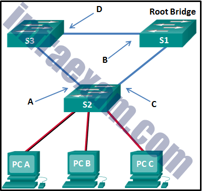
Refer to the exhibit. What are the possible port roles for ports A, B, C, and D in this RSTP-enabled network?
CCNA 2 v7 SRWE Final Exam Answers 13 - designated, alternate, root, root
- designated, root, alternate, root
- alternate, root, designated, root
- alternate, designated, root, root
Answers Explanation & Hints: Because S1 is the root bridge, B is a designated port, and C and D root ports. RSTP supports a new port type, alternate port in discarding state, that can be port A in this scenario.
-
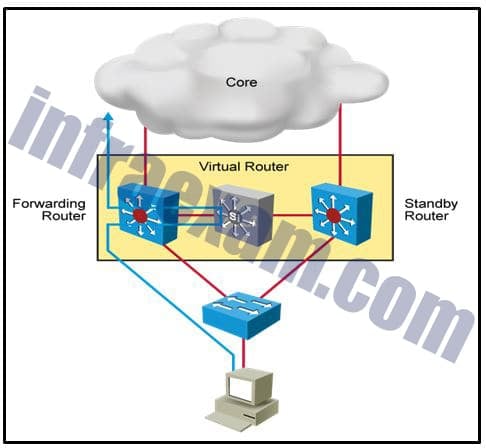
Refer to the exhibit. Which destination MAC address is used when frames are sent from the workstation to the default gateway?
CCNA 2 v7 SRWE Final Exam Answers 10 - MAC address of the virtual router
- MAC addresses of both the forwarding and standby routers
- MAC address of the standby router
- MAC address of the forwarding router
Answers Explanation & Hints: The IP address of the virtual router acts as the default gateway for all the workstations. Therefore, the MAC address that is returned by the Address Resolution Protocol to the workstation will be the MAC address of the virtual router.
-
What is a secure configuration option for remote access to a network device?
- Configure SSH.
- Configure 802.1x.
- Configure an ACL and apply it to the VTY lines.
- Configure Telnet.
Explanation & Hint: To determine the most secure configuration option for remote access to a network device from the options provided:
- Configure SSH (Secure Shell):
- Why It’s Secure: SSH is a protocol that ensures secure network management and communications. It encrypts data, including passwords, to protect against interception and provides secure channel establishment. This makes it highly effective in safeguarding remote access.
- Best Practice: Use SSH version 2 for enhanced security features. Implement strong authentication methods like public key authentication and disable root login where possible.
- Configure 802.1x:
- Why It’s Secure (But Less Relevant): While 802.1x provides robust network access control, primarily for wireless and LAN environments, it’s not typically used for remote device management. It’s excellent for controlling which devices can connect to a network but less applicable for remote administrative access to network devices.
- Configure an ACL (Access Control List) and Apply It to the VTY (Virtual Terminal) Lines:
- Why It’s Secure: Applying ACLs to VTY lines is a good practice for enhancing security. It restricts remote access to the device by allowing only specified IP addresses to connect. This helps in mitigating unauthorized access.
- Best Practice: Regularly update the ACL to ensure it reflects current network policies and trusted hosts.
- Configure Telnet:
- Why It’s Insecure: Telnet is an older protocol that transmits data, including login credentials, in plain text. This lack of encryption makes it vulnerable to eavesdropping and man-in-the-middle attacks. In modern network environments, Telnet is considered insecure and should be avoided for remote device management.
Conclusion: The most secure option among those listed is to configure SSH for remote access to a network device. It provides strong encryption and secure authentication mechanisms, making it the standard for secure remote management. Using ACLs on VTY lines as an additional layer of security can further enhance your network’s defense against unauthorized access.
- Configure SSH (Secure Shell):
-
After a host has generated an IPv6 address by using the DHCPv6 or SLAAC process, how does the host verify that the address is unique and therefore usable?
- The host checks the local neighbor cache for the learned address and if the address is not cached, it it considered unique.
- The host sends an ICMPv6 neighbor solicitation message to the DHCP or SLAAC-learned address and if no neighbor advertisement is returned, the address is considered unique.
- The host sends an ICMPv6 echo request message to the DHCPv6 or SLAAC-learned address and if no reply is returned, the address is considered unique.
- The host sends an ARP broadcast to the local link and if no hosts send a reply, the address is considered unique.
Answers Explanation & Hints: Before a host can actually configure and use an IPv6 address learned through SLAAC or DHCP, the host must verify that no other host is already using that address. To verify that the address is indeed unique, the host sends an ICMPv6 neighbor solicitation to the address. If no neighbor advertisement is returned, the host considers the address to be unique and configures it on the interface.
-
Refer to the exhibit. Host A has sent a packet to host B. What will be the source MAC and IP addresses on the packet when it arrives at host B?

CCNA 2 v7 SRWE Final Exam Answers 02 - Source MAC: 00E0.FE91.7799
Source IP: 10.1.1.10 - Source MAC: 00E0.FE91.7799
Source IP: 10.1.1.1 - Source MAC: 00E0.FE10.17A3
Source IP: 10.1.1.10 - Source MAC: 00E0.FE10.17A3
Source IP: 192.168.1.1 - Source MAC: 00E0.FE91.7799
Source IP: 192.168.1.1Explanation: As a packet traverses the network, the Layer 2 addresses will change at every hop as the packet is de-encapsulated and re-encapsulated, but the Layer 3 addresses will remain the same.
- Source MAC: 00E0.FE91.7799
-
After attaching four PCs to the switch ports, configuring the SSID and setting authentication properties for a small office network, a technician successfully tests the connectivity of all PCs that are connected to the switch and WLAN. A firewall is then configured on the device prior to connecting it to the Internet. What type of network device includes all of the described features?
- standalone wireless access point
- firewall appliance
- switch
- wireless router
-
Explanation & Hint: The type of network device that includes all of the described features – connecting multiple PCs to switch ports, configuring an SSID (Service Set Identifier) for wireless networking, setting up authentication properties, and integrating a firewall – is most likely a wireless router. Here’s why:
- Standalone Wireless Access Point: While a wireless access point would allow for the configuration of an SSID and support wireless connectivity, it typically does not include switch ports for direct PC connections, nor does it integrate a firewall for Internet connectivity. It’s mainly focused on providing wireless access to a network.
- Firewall Appliance: A firewall appliance is primarily designed to provide network security. It monitors and controls incoming and outgoing network traffic based on predetermined security rules. Although some advanced firewall appliances may offer additional features, they typically don’t provide wireless access or switch ports for direct PC connections as their primary function.
- Switch: A switch is a network device that connects devices together on a computer network by using packet switching to receive and forward data to the destination device. However, standard switches do not provide wireless connectivity or have built-in firewall capabilities.
- Wireless Router: A wireless router combines the functions of a router (directing traffic between networks, typically including Internet connectivity), a switch (providing multiple Ethernet ports for wired connections), and a wireless access point (allowing devices to connect to the network wirelessly). It also often includes firewall capabilities to protect the network from external threats. This makes it the most fitting choice for the scenario described, as it encompasses all the functionalities mentioned: switch ports, wireless SSID and authentication configuration, and a firewall for Internet connectivity.
Therefore, a wireless router is the type of network device that would include all the described features for a small office network setup.
-
Which wireless encryption method is the most secure?
- WPA2 with AES
- WPA2 with TKIP
- WEP
- WPA
-
Explanation & Hint: The most secure wireless encryption method among the ones listed is WPA2 with AES (Advanced Encryption Standard). Here’s a brief overview of each option and why WPA2 with AES is the best choice:
- WEP (Wired Equivalent Privacy):
- Security Level: Very low. WEP is an outdated and insecure protocol. It uses weak encryption techniques and can be easily cracked with modern hacking tools.
- Usage Recommendation: Should not be used due to its vulnerabilities.
- WPA (Wi-Fi Protected Access):
- Security Level: Better than WEP but still not highly secure. WPA was a temporary security enhancement over WEP. It uses TKIP (Temporal Key Integrity Protocol) which has known vulnerabilities.
- Usage Recommendation: Only use if WPA2 is not available, but it’s not recommended due to security concerns.
- WPA2 with TKIP:
- Security Level: More secure than WPA, but TKIP is still a less secure encryption method compared to AES. WPA2 is an updated version of WPA and provides better security.
- Usage Recommendation: Better than WPA or WEP, but not the best option available.
- WPA2 with AES:
- Security Level: Highest among the listed options. AES is a more advanced and secure encryption algorithm. WPA2 with AES is currently considered the industry standard for wireless network security.
- Usage Recommendation: Strongly recommended for securing wireless networks. Provides robust security and is widely supported by modern wireless devices.
In summary, WPA2 with AES offers the strongest security and is the recommended choice for wireless network encryption. It combines the improved security protocol of WPA2 with the advanced encryption capabilities of AES, making it the best option among those listed.
- WEP (Wired Equivalent Privacy):
-
Match the description to the correct VLAN type. (Not all options are used.)
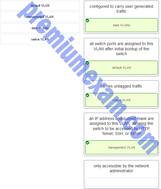
CCNA 2 v7 SRWE Final Exam Answers 003 Answers Explanation & Hints: A data VLAN is configured to carry user-generated traffic. A default VLAN is the VLAN where all switch ports belong after the initial boot up of a switch loading the default configuration. A native VLAN is assigned to an 802.1Q trunk port, and untagged traffic is placed on it. A management VLAN is any VLAN that is configured to access the management capabilities of a switch. An IP address and subnet mask are assigned to it, allowing the switch to be managed via HTTP, Telnet, SSH, or SNMP.
-
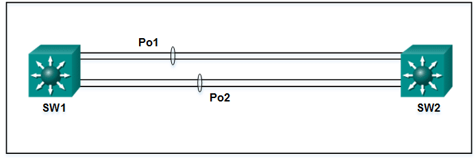
Refer to the exhibit. A network administrator has connected two switches together using EtherChannel technology. If STP is running, what will be the end result?
CCNA 2 v7 SRWE Final Exam Answers 000 - The switches will load balance and utilize both EtherChannels to forward packets.
- Both port channels will shutdown.
- The resulting loop will create a broadcast storm.
- STP will block one of the redundant links.
Answers Explanation & Hints: Cisco switches support two protocols for negotiating a channel between two switches: LACP and PAgP. PAgP is Cisco-proprietary. In the topology shown, the switches are connected to each other using redundant links. By default, STP is enabled on switch devices. STP will block redundant links to prevent loops.
-
What are three techniques for mitigating VLAN attacks? (Choose three.)
- Enable BPDU guard.
- Set the native VLAN to an unused VLAN.
- Use private VLANs.
- Disable DTP.
- Enable Source Guard.
- Enable trunking manually.
Answers Explanation & Hints: Mitigating a VLAN attack can be done by disabling Dynamic Trunking Protocol (DTP), manually setting ports to trunking mode, and by setting the native VLAN of trunk links to VLANs not in use.
-
An administrator is trying to remove configurations from a switch. After using the command erase startup-config and reloading the switch, the administrator finds that VLANs 10 and 100 still exist on the switch. Why were these VLANs not removed?
- These VLANs cannot be deleted unless the switch is in VTP client mode.
- These VLANs can only be removed from the switch by using the no vlan 10 and no vlan 100 commands.
- These VLANs are default VLANs that cannot be removed.
- Because these VLANs are stored in a file that is called vlan.dat that is located in flash memory, this file must be manually deleted.
Answers Explanation & Hints: Standard range VLANs (1-1005) are stored in a file that is called vlan.dat that is located in flash memory. Erasing the startup configuration and reloading a switch does not automatically remove these VLANs. The vlan.dat file must be manually deleted from flash memory and then the switch must be reloaded.
-
Refer to the exhibit. Which static route would an IT technician enter to create a backup route to the 172.16.1.0 network that is only used if the primary RIP learned route fails?
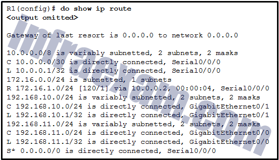
CCNA 2 v7 SRWE Final Exam Answers 20 - ip route 172.16.1.0 255.255.255.0 s0/0/0
- ip route 172.16.1.0 255.255.255.0 s0/0/0 91
- ip route 172.16.1.0 255.255.255.0 s0/0/0 111
- ip route 172.16.1.0 255.255.255.0 s0/0/0 121
Answers Explanation & Hints: A backup static route is called a floating static route. A floating static route has an administrative distance greater than the administrative distance of another static route or dynamic route.
-
Refer to the exhibit. In addition to static routes directing traffic to networks 10.10.0.0/16 and 10.20.0.0/16, Router HQ is also configured with the following command: ip route 0.0.0.0 0.0.0.0 serial 0/1/1 What is the purpose of this command?

CCNA 2 v7 SRWE Final Exam Answers 05 - Packets from the 10.10.0.0/16 network will be forwarded to network 10.20.0.0/16, and packets from the 10.20.0.0/16 network will be forwarded to network 10.10.0.0/16.
- Packets that are received from the Internet will be forwarded to one of the LANs connected to R1 or R2.
- Packets with a destination network that is not 10.10.0.0/16 or is not 10.20.0.0/16 or is not a directly connected network will be forwarded to the Internet.
- Packets that are destined for networks that are not in the routing table of HQ will be dropped.
-
Explanation & Hint: The command
ip route 0.0.0.0 0.0.0.0 serial 0/1/1configured on Router HQ in the network diagram is used to set a default route. This default route is often referred to as the “gateway of last resort.” The purpose of this command is to specify that any packets with a destination network that is not found in the routing table should be forwarded to the next-hop address associated with the Serial 0/1/1 interface.Here are the options analyzed:
- Packets from the 10.10.0.0/16 network will be forwarded to network 10.20.0.0/16, and packets from the 10.20.0.0/16 network will be forwarded to network 10.10.0.0/16.
- This statement is incorrect because the command does not specify any conditional forwarding between the two LAN networks. It is a default route for any unknown networks, not a route between the two specified networks.
- Packets that are received from the Internet will be forwarded to one of the LANs connected to R1 or R2.
- This statement is not entirely accurate. The command does not necessarily forward packets from the Internet to the LANs; instead, it dictates what HQ does with packets for which it has no specific route.
- Packets with a destination network that is not 10.10.0.0/16 or is not 10.20.0.0/16 or is not a directly connected network will be forwarded to the Internet.
- This option is correct. Any packet that does not match a more specific route in the routing table of HQ, which includes the two LAN networks and any directly connected networks, will be forwarded to the next hop specified by the default route, which in this case is likely the Internet.
- Packets that are destined for networks that are not in the routing table of HQ will be dropped.
- This statement is incorrect because the purpose of a default route is to prevent packets from being dropped when their destination networks are not in the routing table. Instead, they are sent to the default gateway.
Therefore, the purpose of the
ip route 0.0.0.0 0.0.0.0 serial 0/1/1command is to forward packets with a destination network that is not known in the router’s routing table (not 10.10.0.0/16, not 10.20.0.0/16, or not a directly connected network) to the Internet. - Packets from the 10.10.0.0/16 network will be forwarded to network 10.20.0.0/16, and packets from the 10.20.0.0/16 network will be forwarded to network 10.10.0.0/16.
-
Refer to the exhibit. A network administrator is configuring inter-VLAN routing on a network. For now, only one VLAN is being used, but more will be added soon. What is the missing parameter that is shown as the highlighted question mark in the graphic?
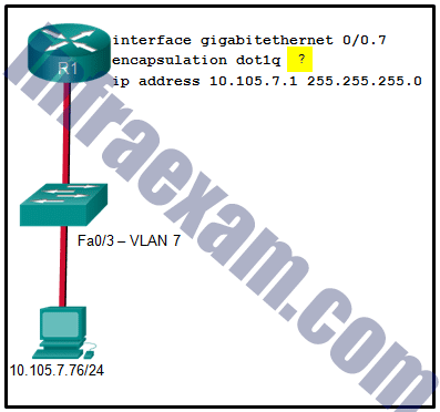
CCNA 2 v7 SRWE Final Exam Answers 04 - It identifies the number of hosts that are allowed on the interface.
- It identifies the type of encapsulation that is used.
- It identifies the subinterface.
- It identifies the native VLAN number.
- It identifies the VLAN number.
Answers Explanation & Hints: The completed command would be encapsulation dot1q 7 . The encapsulation dot1q part of the command enables trunking and identifies the type of trunking to use. The 7 identifies the VLAN number.
-
Match the link state to the interface and protocol status. (Not all options are used.)
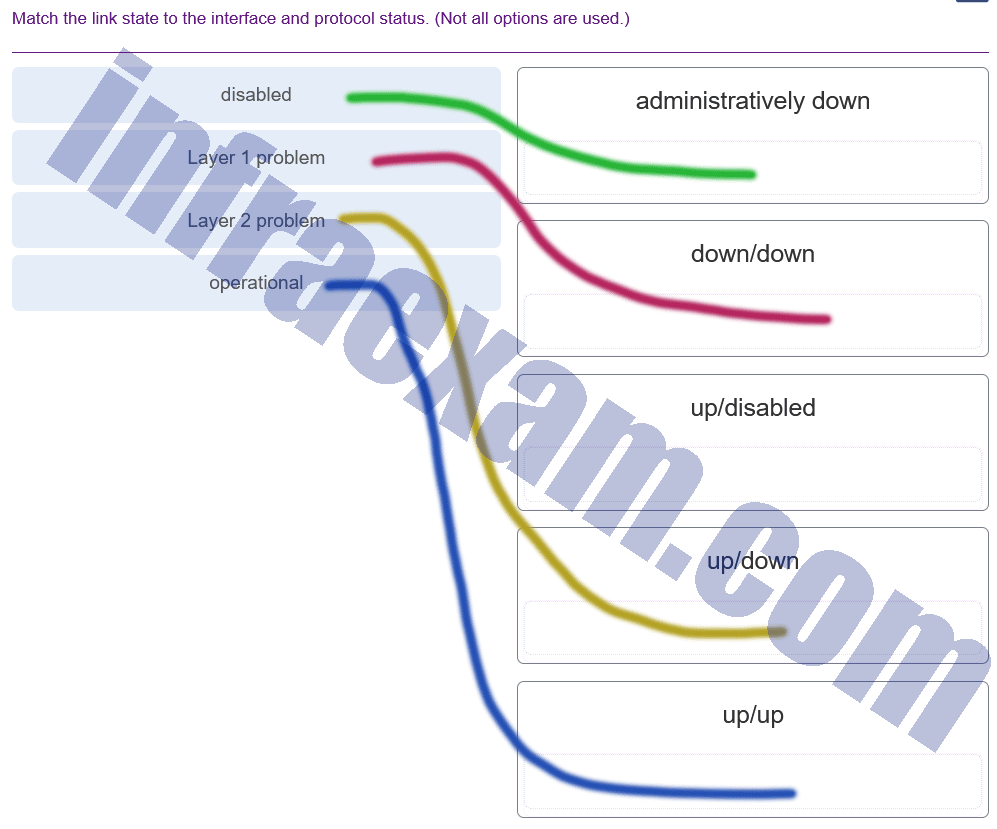
CCNA 2 v7 SRWE Final Exam Answers 002 Explanation: The login and password cisco commands are used with Telnet switch configuration, not SSH configuration.
-
Refer to the exhibit. How is a frame sent from PCA forwarded to PCC if the MAC address table on switch SW1 is empty?
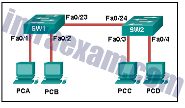
CCNA 2 v7 SRWE Final Exam Answers 07 - SW1 forwards the frame directly to SW2. SW2 floods the frame to all ports connected to SW2, excluding the port through which the frame entered the switch.
- SW1 floods the frame on all ports on the switch, excluding the interconnected port to switch SW2 and the port through which the frame entered the switch.
- SW1 drops the frame because it does not know the destination MAC address.
- SW1 floods the frame on all ports on SW1, excluding the port through which the frame entered the switch.
Answers Explanation & Hints: When a switch powers on, the MAC address table is empty. The switch builds the MAC address table by examining the source MAC address of incoming frames. The switch forwards based on the destination MAC address found in the frame header. If a switch has no entries in the MAC address table or if the destination MAC address is not in the switch table, the switch will forward the frame out all ports except the port that brought the frame into the switch.
-
Match the DHCP message types to the order of the DHCPv4 process. (Not all options are used.)
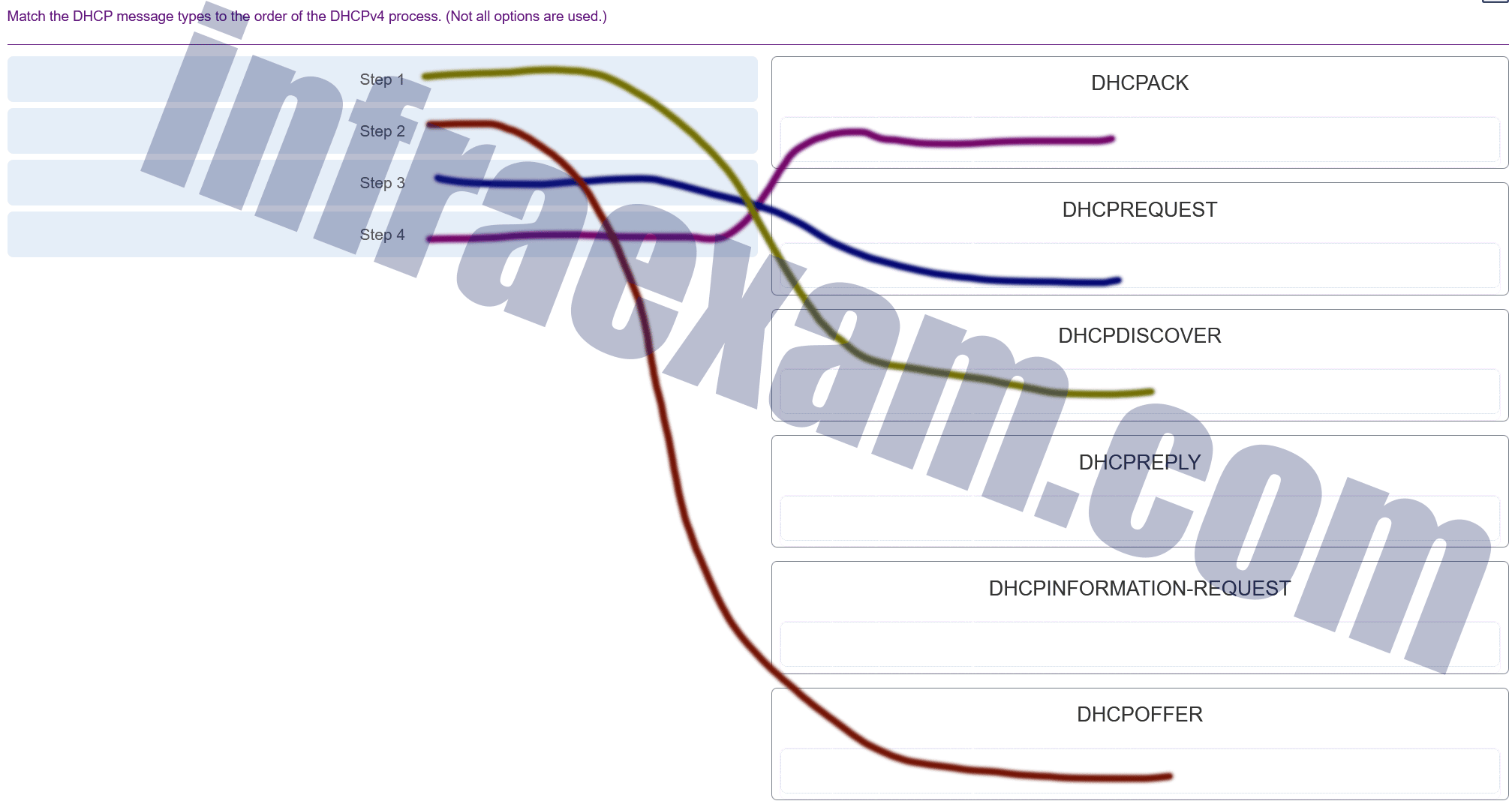
CCNA 2 SRWE v7 Modules 7 – 9 – Available and Reliable Networks Exam Answers 007 Answers Explanation & Hints: The broadcast DHCPDISCOVER message finds DHCPv4 servers on the network. When the DHCPv4 server receives a DHCPDISCOVER message, it reserves an available IPv4 address to lease to the client and sends the unicast DHCPOFFER message to the requesting client. When the client receives the DHCPOFFER from the server, it sends back a DHCPREQUEST. On receiving the DHCPREQUEST message the server replies with a unicast DHCPACK message. DHCPREPLY and DHCPINFORMATION-REQUEST are DHCPv6 messages.
-
A network administrator is configuring a WLAN. Why would the administrator disable the broadcast feature for the SSID?
- to reduce the risk of interference by external devices such as microwave ovens
- to reduce the risk of unauthorized APs being added to the network
- to provide privacy and integrity to wireless traffic by using encryption
- to eliminate outsiders scanning for available SSIDs in the area
-
Explanation & Hint: The administrator would disable the broadcast feature for the SSID primarily to eliminate outsiders scanning for available SSIDs in the area. Disabling the SSID broadcast makes the network name (SSID) invisible to wireless-enabled devices during a passive scan. It doesn’t provide encryption or protect against interference from external devices; instead, it acts as a basic measure to hide the network from casual discovery, which can slightly increase security by obscurity.
Here’s a look at why the other options are not correct:
- To reduce the risk of interference by external devices such as microwave ovens: Interference from electronic devices affects the wireless signal’s quality but has nothing to do with SSID broadcast. Disabling SSID broadcast does not mitigate such interference.
- To reduce the risk of unauthorized APs being added to the network: Disabling SSID broadcast does not prevent unauthorized access points (APs) from being added to the network. Network security protocols and access control methods are necessary to prevent unauthorized APs.
- To provide privacy and integrity to wireless traffic by using encryption: Disabling SSID broadcast does not encrypt wireless traffic. Privacy and integrity are achieved through encryption protocols like WPA2/WPA3 with AES, not by hiding the SSID.
-
Compared with dynamic routes, what are two advantages of using static routes on a router? (Choose two.)
- They automatically switch the path to the destination network when the topology changes.
- They improve the efficiency of discovering neighboring networks.
- They use fewer router resources.
- They improve network security.
- They take less time to converge when the network topology changes.
-
Explanation & Hint: The two advantages of using static routes on a router compared to dynamic routes are:
- They use fewer router resources: Static routes are manually configured and do not require the overhead of a routing protocol, which means they use less CPU and memory resources on the router.
- They improve network security: Static routes add a measure of security because they allow the network administrator to control the routing in a very precise manner, which can prevent unwanted routing updates or potential routing loops. Unauthorized networks cannot be advertised since routing decisions are made by the administrator and not a routing protocol.
The other options provided are advantages of dynamic routing, not static routing:
- They automatically switch the path to the destination network when the topology changes: This is an advantage of dynamic routing, as routing protocols can adapt to changes in the network topology automatically.
- They improve the efficiency of discovering neighboring networks: Dynamic routing protocols are designed to discover neighboring routers and networks efficiently. Static routes do not have this capability since they are manually configured and do not dynamically discover other networks.
- They take less time to converge when the network topology changes: Dynamic routes have the advantage of convergence, which is the process of routers updating their routing tables after a change in the network topology. Static routes do not converge because they are not aware of network topology changes unless manually updated by the network administrator.
-
Refer to the exhibit. Which route was configured as a static route to a specific network using the next-hop address?
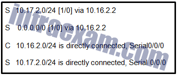
CCNA 2 v7 SRWE Final Exam Answers 17 - S 0.0.0.0/0 [1/0] via 10.16.2.2
- S 10.17.2.0/24 is directly connected, Serial 0/0/0
- C 10.16.2.0/24 is directly connected, Serial0/0/0
- S 10.17.2.0/24 [1/0] via 10.16.2.2
Explanation: The C in a routing table indicates an interface that is up and has an IP address assigned. The S in a routing table signifies that a route was installed using the ip route command. Two of the routing table entries shown are static routes to a specific destination (the 10.17.2.0 network). The entry that has the S denoting a static route and [1/0] was configured using the next-hop address. The other entry (S 10.17.2.0/24 is directly connected, Serial 0/0/0) is a static route configured using the exit interface. The entry with the 0.0.0.0 route is a default static route which is used to send packets to any destination network that is not specifically listed in the routing table.
-
Refer to the exhibit. What is the metric to forward a data packet with the IPv6 destination address 2001:DB8:ACAD:E:240:BFF:FED4:9DD2?
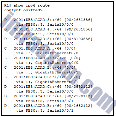
CCNA 2 v7 SRWE Final Exam Answers 03 - 90
- 128
- 2170112
- 2681856
- 2682112
- 3193856
Explanation: The IPv6 destination address 2001:DB8:ACAD:E:240:BFF:FED4:9DD2 belongs to the network of 2001:DB8:ACAD:E::/64. In the routing table, the route to forward the packet has Serial 0/0/1 as an exit interface and 2682112 as the cost.
-
A static route has been configured on a router. However, the destination network no longer exists. What should an administrator do to remove the static route from the routing table?
- Remove the route using the no ip route command.
- Change the administrative distance for that route.
- Nothing. The static route will go away on its own.
- Change the routing metric for that route.
-
Explanation & Hint: To remove a static route from the routing table on a router, an administrator should use the “no ip route” command. This command effectively deletes the specified static route from the router’s configuration, ensuring that it is no longer used for routing decisions.
The other options are not correct for this scenario:
- Changing the administrative distance or the routing metric will not remove the route but will affect how it is prioritized compared to other routes.
- Static routes do not go away on their own; they remain in the router’s configuration until they are manually removed or the configuration is changed.
-
Which two statements are characteristics of routed ports on a multilayer switch? (Choose two.)
- In a switched network, they are mostly configured between switches at the core and distribution layers.
- They are used for point-to-multipoint links.
- They are not associated with a particular VLAN.
- They support subinterfaces, like interfaces on the Cisco IOS routers.
- The interface vlan <vlan number> command has to be entered to create a VLAN on routed ports.
-
Explanation & Hint: The two statements that are characteristics of routed ports on a multilayer switch are:
- They are not associated with a particular VLAN: Routed ports on a multilayer switch operate at Layer 3 (the network layer) and are used to route traffic between different networks. Unlike switch ports, which are associated with a specific VLAN (Layer 2), routed ports do not belong to a VLAN.
- They support subinterfaces, like interfaces on the Cisco IOS routers: Routed ports on a multilayer switch can be configured with subinterfaces, similar to how router interfaces are configured. This allows for more complex routing scenarios, such as inter-VLAN routing and encapsulation methods like 802.1Q VLAN tagging.
The other statements are not accurate descriptions of routed ports on a multilayer switch:
- “In a switched network, they are mostly configured between switches at the core and distribution layers” is more applicable to switch ports, not necessarily routed ports.
- “They are used for point-to-multipoint links” is not a defining characteristic of routed ports.
- “The interface vlan <vlan number> command has to be entered to create a VLAN on routed ports” is incorrect, as routed ports are not associated with VLANs; this command is used for creating VLAN interfaces (SVIs) for VLAN routing on switches.
-
Refer to the exhibit. After attempting to enter the configuration that is shown in router RTA, an administrator receives an error and users on VLAN 20 report that they are unable to reach users on VLAN 30. What is causing the problem?
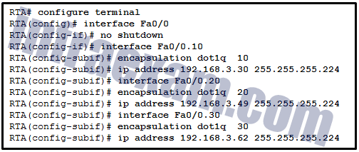
CCNA 2 v7 SRWE Final Exam Answers 01 - The no shutdown command should have been issued on Fa0/0.20 and Fa0/0.30.
- There is no address on Fa0/0 to use as a default gateway.
- Dot1q does not support subinterfaces.
- RTA is using the same subnet for VLAN 20 and VLAN 30.
-
Explanation & Hint: The error users on VLAN 20 are experiencing in reaching users on VLAN 30 is likely due to the fact that RTA is using the same subnet for both VLAN 20 and VLAN 30.
In the configuration provided in the exhibit, both subinterfaces for VLAN 20 and VLAN 30 are assigned IP addresses from the same subnet:
- VLAN 20 is assigned 192.168.3.49/27
- VLAN 30 is assigned 192.168.3.62/27
With a subnet mask of 255.255.255.224 (/27), both of these IP addresses fall within the same subnet range (192.168.3.32 to 192.168.3.63), which means that the router cannot distinguish between the two separate VLANs as they do not have unique IP subnets.
To resolve this issue, the administrator needs to assign a unique IP subnet to each VLAN to ensure proper routing between them.
-
Refer to the exhibit. Which trunk link will not forward any traffic after the root bridge election process is complete?
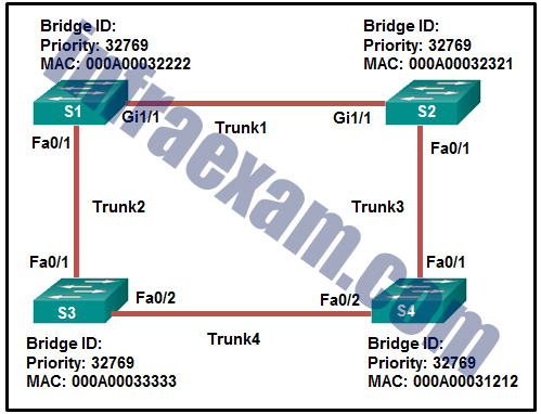
CCNA 2 v7 SRWE Final Exam Answers 14 - Trunk1
- Trunk2
- Trunk3
- Trunk4
-
Explanation & Hint: Because the path cost between S1 and S2 is 4, and we assume the path costs on the network are the default costs based on Ethernet link speeds (which is typically higher for slower links), then S3 will compare the path cost to the root bridge through Trunk2 directly to S1 and the path cost going through S4 and then S2 to S1 (Trunk4 to Trunk1).
Since you’ve mentioned that the correct answer is Trunk2, we would deduce the following:
- The path cost for S3 to reach S1 via Trunk2 is higher than reaching S1 via S4 and S2 (Trunk4 to Trunk3 to Trunk1).
- Given that S1 to S2 is 4, and assuming all links have the same cost, the total cost for S3 to reach S1 via S4 and S2 would be 12 (4 for Trunk4, 4 for Trunk3, and 4 for Trunk1).
- For Trunk2 to be blocked, its path cost would have to be higher than 12, making the path through S4 and S2 more favorable despite being longer in terms of hop count.
This is contrary to what we would expect in a typical Ethernet network, where the direct path (which is usually the shortest path) between two switches has the lowest cost, and thus would be chosen for forwarding traffic. However, if manual path cost configuration is applied to make the direct path cost higher, then STP would determine a different forwarding path, which can lead to a non-direct link being chosen as the root port, and the direct link (Trunk2) being put in a blocking state.
Therefore, based on the specific path costs you’ve provided and the reported correct answer, it seems there has been a manual configuration that has adjusted the path costs to make the indirect path from S3 to S1 via S4 and S2 more favorable than the direct path via Trunk2.
-
A network administrator is preparing the implementation of Rapid PVST+ on a production network. How are the Rapid PVST+ link types determined on the switch interfaces?
- Link types can only be determined if PortFast has been configured.
- Link types can only be configured on access ports configured with a single VLAN.
- Link types are determined automatically.
- Link types must be configured with specific port configuration commands.
Explanation: When Rapid PVST+ is being implemented, link types are automatically determined but can be specified manually. Link types can be either point-to-point, shared, or edge.
-
Which two types of spanning tree protocols can cause suboptimal traffic flows because they assume only one spanning-tree instance for the entire bridged network? (Choose two.)
- STP
- Rapid PVST+
- MSTP
- PVST+
- RSTP
-
Explanation & Hint: The two types of Spanning Tree Protocols that can cause suboptimal traffic flows because they assume only one spanning-tree instance for the entire bridged network are:
- STP (Standard Spanning Tree Protocol): The original Spanning Tree Protocol, as defined in IEEE 802.1D, creates a single spanning-tree instance for the entire network, regardless of the number of VLANs. This can lead to suboptimal paths in networks where multiple VLANs are configured, as it doesn’t allow for load balancing across different VLANs.
- RSTP (Rapid Spanning Tree Protocol): Although RSTP (IEEE 802.1w) is an evolution of STP that provides faster convergence, it still operates a single instance of spanning-tree for the entire network. Like STP, RSTP does not create separate spanning-trees for each VLAN, which can lead to suboptimal traffic flows in networks with multiple VLANs.
On the other hand:
- PVST+ (Per VLAN Spanning Tree Plus) and Rapid PVST+: These are Cisco enhancements to STP and RSTP that maintain a separate spanning-tree instance for each VLAN. This allows for more optimal traffic flow as it can balance load across different VLANs.
- MSTP (Multiple Spanning Tree Protocol): Defined in IEEE 802.1s, MSTP also allows for multiple spanning-tree instances but groups VLANs into instances, providing a balance between single-instance STP/RSTP and one-instance-per-VLAN PVST+/Rapid PVST+. This can be more scalable than PVST+ in large networks with many VLANs.
Therefore, STP and RSTP are the protocols that would fit the criteria of assuming only one spanning-tree instance for the entire bridged network, potentially leading to suboptimal traffic flows in a VLAN-rich environment.
-
What action takes place when the source MAC address of a frame entering a switch appears in the MAC address table associated with a different port?
- The switch purges the entire MAC address table.
- The switch replaces the old entry and uses the more current port.
- The switch updates the refresh timer for the entry.
- The switch forwards the frame out of the specified port.
-
Explanation & Hint: When a switch receives a frame and the source MAC address of that frame is already in the MAC address table but associated with a different port, the switch will replace the old entry and use the more current port.
In other words, the switch updates its MAC address table to reflect the new port information. This process ensures that the switch’s MAC address table remains accurate and up to date with the current network topology and device connections.
The other options provided do not accurately describe the typical behavior of a switch in this scenario:
- The switch purges the entire MAC address table: This would be an inefficient and disruptive response to a common event and is not how switches typically handle changes in the location of MAC addresses.
- The switch updates the refresh timer for the entry: The refresh timer is updated whenever a frame from the same MAC address is received on the same port, not when the MAC address is seen on a different port.
- The switch forwards the frame out of the specified port: The switch forwards frames based on the destination MAC address, not the source MAC address. The action described here does not pertain to updating the MAC address table in response to seeing a known source MAC address on a new port.
-
A network administrator configures the port security feature on a switch. The security policy specifies that each access port should allow up to two MAC addresses. When the maximum number of MAC addresses is reached, a frame with the unknown source MAC address is dropped and a notification is sent to the syslog server. Which security violation mode should be configured for each access port?
- warning
- restrict
- shutdown
- protect
-
Explanation & Hint: The port security violation mode that fits the security policy described by the network administrator is restrict.
In restrict mode, when the maximum number of allowed MAC addresses is reached on the port, the port will continue to forward traffic for the currently learned MAC addresses but will drop packets with unknown source MAC addresses and increment the security violation count. It also has the capability to send a syslog message.
Here’s a brief explanation of each violation mode for clarity:
- Protect: When the maximum number of MAC addresses is reached, frames with unknown source addresses are dropped until some MAC addresses are removed from the address table. There is no notification sent that a security violation has occurred.
- Restrict: Similar to protect mode, but it also increments the violation counter and logs a syslog message.
- Shutdown: The port is errdisabled (administratively shut down) and it must be manually reenabled or automatically recovered if auto-recovery is configured. It also sends a syslog message.
- Warning: This is not a standard port security violation mode on Cisco switches.
Given the requirements for the security policy—dropping frames with unknown source MAC addresses upon reaching the limit and sending a notification without shutting down the port—the correct mode to use is restrict.
-
Which network attack is mitigated by enabling BPDU guard?
- rogue switches on a network
- rogue DHCP servers on a network
- MAC address spoofing
- CAM table overflow attacks
Explanation: There are several recommended STP stability mechanisms to help mitigate STP manipulation attacks:
- PortFast – used to immediately bring an interface configured as an access or trunk port to the forwarding state from a blocking state. Applied to all end-user ports.
- BPDU guard – immediately error-disables a port that receives a BPDU. Applied to all end-user ports.The receipt of BPDUs may be part of an unauthorized attempt to add a switch to the network.
- Root guard – prevents a switch from becoming the root switch. Applied to all ports where the root switch should not be located.
- Loop guard – detects unidirectional links to prevent alternate or root ports from becoming designated ports. Applied to all ports that are or can become nondesignated.
-
A network administrator uses the spanning-tree portfast bpduguard default global configuration command to enable BPDU guard on a switch. However, BPDU guard is not activated on all access ports. What is the cause of the issue?
- PortFast is not configured on all access ports.
- Access ports belong to different VLANs.
- BPDU guard needs to be activated in the interface configuration command mode.
- Access ports configured with root guard cannot be configured with BPDU guard.
-
Explanation & Hint: The cause of the issue where BPDU guard is not activated on all access ports, even after using the
spanning-tree portfast bpduguard defaultglobal configuration command, is likely because PortFast is not configured on all access ports.The
spanning-tree portfast bpduguard defaultcommand globally enables BPDU guard on all ports that have PortFast enabled. If PortFast has not been enabled on a particular access port, then BPDU guard will not be automatically activated on that port as a result of the global command.Here’s the reason the other options are less likely to be the cause:
- Access ports belong to different VLANs: BPDU guard and PortFast are features that can be applied to access ports irrespective of their VLAN assignments.
- BPDU guard needs to be activated in the interface configuration command mode: While BPDU guard can indeed be activated on an interface-by-interface basis, the global command is designed to automatically enable BPDU guard on all ports that have PortFast enabled, without the need for per-interface configuration.
- Access ports configured with root guard cannot be configured with BPDU guard: While it is true that root guard and BPDU guard are mutually exclusive on a per-port basis, the command in question wouldn’t be affected by root guard configuration. However, if root guard is already configured on some ports, BPDU guard would not be able to be activated on those ports until root guard is removed.
Therefore, the most likely reason for BPDU guard not being activated on all access ports is because PortFast has not been enabled on those ports. The administrator would need to ensure that PortFast is enabled on all access ports where BPDU guard is desired.
-
A new Layer 3 switch is connected to a router and is being configured for interVLAN routing. What are three of the five steps required for the configuration? (Choose three.) Type A *
- creating SVI interfaces
- creating VLANs
- installing a static route
- adjusting the route metric
- implementing a routing protocol
- modifying the default VLAN
- assigning ports to VLANs
-
Explanation & Hint: For configuring a Layer 3 switch for interVLAN routing, the typical steps include:
- Creating VLANs: VLANs must be created on the switch to logically separate networks before interVLAN routing can occur.
- Creating SVI interfaces: Switched Virtual Interfaces (SVIs) are required for a Layer 3 switch to perform interVLAN routing. An SVI must be created for each VLAN that needs to be routed.
- Assigning ports to VLANs: Physical switch ports need to be assigned to the appropriate VLANs to ensure that devices connected to those ports are part of the correct VLAN.
The other options listed are not primary steps for basic interVLAN routing configuration on a Layer 3 switch:
- Installing a static route: This might be necessary for routing to networks outside of the Layer 3 switch but is not a primary step for enabling interVLAN routing itself.
- Adjusting the route metric: This would be relevant if multiple routing paths were available and if there was a need to influence the routing decisions made by dynamic routing protocols.
- Implementing a routing protocol: This might be necessary for larger networks with multiple routers and complex topologies but is not a requirement for interVLAN routing on a single Layer 3 switch.
- Modifying the default VLAN: The default VLAN (VLAN 1) usually requires no modification for interVLAN routing to function.
So, the three correct steps from the choices given would be:
- Creating VLANs
- Creating SVI interfaces
- Assigning ports to VLANs
-
A new Layer 3 switch is connected to a router and is being configured for interVLAN routing. What are three of the five steps required for the configuration? (Choose three.) Type B
- installing a static route
- assigning the ports to the native VLAN
- entering “no switchport” on the port connected to the router
- modifying the default VLAN
- assigning ports to VLANs
- enabling IP routing
- adjusting the route metric
-
Explanation & Hint: For configuring interVLAN routing on a new Layer 3 switch that is connected to a router, the following steps are typically required:
- Enabling IP routing: This step enables the Layer 3 switch to perform routing functions, allowing it to route traffic between different VLANs. This is usually done with the
ip routingcommand in global configuration mode. - Assigning ports to VLANs: This involves configuring the switch ports to belong to the appropriate VLANs. This is essential for defining which devices belong to which VLANs, and it’s a key step in setting up VLANs and interVLAN routing.
- Entering “no switchport” on the port connected to the router: This command is used to convert a Layer 2 switch port into a Layer 3 interface (routed port). It’s necessary for the interface that will connect to the router, as it allows for routing between the switch and the router.
The other options listed are not primary steps for setting up basic interVLAN routing:
- Installing a static route: While this may be necessary in some scenarios to direct traffic to specific networks, especially those that are not directly connected, it’s not a primary step for basic interVLAN routing setup.
- Assigning the ports to the native VLAN: This is more related to trunk ports configuration and is not directly required for basic interVLAN routing.
- Modifying the default VLAN: This is usually not required for enabling interVLAN routing. The default VLAN (usually VLAN 1) can function without modifications.
- Adjusting the route metric: This is relevant in dynamic routing scenarios to influence routing decisions but is not a direct requirement for setting up interVLAN routing on a Layer 3 switch.
Therefore, the three steps necessary for configuring interVLAN routing in this scenario are enabling IP routing, assigning ports to VLANs, and entering “no switchport” on the port connected to the router.
- Enabling IP routing: This step enables the Layer 3 switch to perform routing functions, allowing it to route traffic between different VLANs. This is usually done with the
-
A new Layer 3 switch is connected to a router and is being configured for interVLAN routing. What are three of the five steps required for the configuration? (Choose three.) Type C
- assigning ports to VLANs
- assigning the ports to the native VLAN
- modifying the default VLAN
- deleting the default VLAN
- enabling IP routing
- installing a static route
- entering “no switchport” on the port connected to the router
-
Explanation & Hint: For configuring interVLAN routing on a new Layer 3 switch that’s connected to a router, the following steps are typically involved:
- Enabling IP routing: This is a crucial step that enables the Layer 3 switch to perform routing functions. By default, a Layer 3 switch operates like a Layer 2 switch. Enabling IP routing allows the switch to route traffic between different VLANs. This is usually done with the
ip routingcommand in the global configuration mode. - Assigning ports to VLANs: This involves configuring the switch ports that connect to devices in different VLANs to the appropriate VLANs. This is done by entering the interface configuration for each port and using the
switchport access vlan [VLAN_ID]command. - Entering “no switchport” on the port connected to the router: This command is used on the interface that will connect to the router to turn it into a Layer 3 interface (routed port) rather than a Layer 2 interface (switch port). This is necessary for the router and the switch to route traffic between them.
The other options are generally not required for basic interVLAN routing setup:
- Assigning the ports to the native VLAN: This is more relevant for trunk ports and is not directly related to setting up interVLAN routing.
- Modifying the default VLAN or Deleting the default VLAN: Neither of these actions is typically necessary for enabling interVLAN routing. The default VLAN (usually VLAN 1) functions well for routing without any modifications.
- Installing a static route: While static routes may be necessary for directing traffic to specific networks, especially those not directly connected, it’s not a primary step for setting up interVLAN routing on the switch itself.
Therefore, the three steps necessary for configuring interVLAN routing in this scenario are enabling IP routing, assigning ports to VLANs, and entering “no switchport” on the port connected to the router.
- Enabling IP routing: This is a crucial step that enables the Layer 3 switch to perform routing functions. By default, a Layer 3 switch operates like a Layer 2 switch. Enabling IP routing allows the switch to route traffic between different VLANs. This is usually done with the
-
A new Layer 3 switch is connected to a router and is being configured for interVLAN routing. What are three of the five steps required for the configuration? (Choose three.) Type D
- installing a static route
- enabling IP routing
- modifying the default VLAN
- implementing a routing protocol
- assigning ports to VLANs
- assigning the ports to the native VLAN
- creating SVI interfaces
-
Explanation & Hint: For configuring interVLAN routing on a new Layer 3 switch that is connected to a router, the three key steps from the options provided are:
- Enabling IP routing: This is essential for the Layer 3 switch to perform routing functions. It allows the switch to route traffic between different VLANs. The command to enable IP routing is usually
ip routingin the global configuration mode. - Creating SVI interfaces: Switch Virtual Interfaces (SVIs) are created for each VLAN that needs routing. SVIs act as the default gateway for VLANs and allow for interVLAN routing on the switch. This involves configuring an IP address for each VLAN interface on the switch.
- Assigning ports to VLANs: This step involves configuring the physical ports on the switch to belong to the appropriate VLANs. This is done by assigning VLANs to individual switch ports, ensuring that devices connected to those ports are part of the correct VLAN.
The other options, while important in certain contexts, are not primary steps for basic interVLAN routing configuration:
- Installing a static route: This might be necessary for routing to networks outside of the Layer 3 switch but is not a primary step for enabling interVLAN routing itself.
- Modifying the default VLAN: This is usually not required for interVLAN routing. The default VLAN (VLAN 1) typically works fine for routing without any modifications.
- Implementing a routing protocol: While useful in dynamic routing scenarios, especially in larger and more complex networks, it is not a necessity for basic interVLAN routing setup on a single Layer 3 switch.
- Assigning the ports to the native VLAN: This typically applies to trunk ports and is not a direct requirement for basic interVLAN routing on a Layer 3 switch.
Therefore, the three steps necessary for configuring interVLAN routing in this scenario are enabling IP routing, creating SVI interfaces, and assigning ports to VLANs.
- Enabling IP routing: This is essential for the Layer 3 switch to perform routing functions. It allows the switch to route traffic between different VLANs. The command to enable IP routing is usually
-
A new Layer 3 switch is connected to a router and is being configured for interVLAN routing. What are three of the five steps required for the configuration? (Choose three.) Type E
- assigning ports to VLANs
- assigning the ports to the native VLAN
- enabling IP routing
- modifying the default VLAN
- installing a static route
- implementing a routing protocol
- creating SVI interfaces
-
Explanation & Hint: For configuring interVLAN routing on a Layer 3 switch, the steps that are typically required include:
- Enabling IP routing: This step is crucial as it allows the Layer 3 switch to route traffic between different VLANs. It is usually done with the
ip routingcommand in the global configuration mode. - Creating SVI interfaces: Switch Virtual Interfaces (SVIs) are required for interVLAN routing. An SVI must be created for each VLAN that you wish to route traffic for. This is done with the
interface vlan [VLAN_ID]command followed by the IP address assignment for that VLAN. - Assigning ports to VLANs: Ports must be assigned to the appropriate VLANs. This is done with the
switchport access vlan [VLAN_ID]command in the interface configuration mode for each access port that is connected to devices in different VLANs.
The other options are not directly related to the initial setup for basic interVLAN routing on a Layer 3 switch:
- Assigning the ports to the native VLAN: This typically relates to trunk ports and is not a direct requirement for basic interVLAN routing on a Layer 3 switch.
- Modifying the default VLAN: This is generally not necessary for enabling interVLAN routing.
- Installing a static route: While static routes may be used to route traffic to specific networks, they are not part of the basic setup for interVLAN routing on the switch itself.
- Implementing a routing protocol: This may be necessary for more complex network designs where multiple routers and Layer 3 switches are present, but it is not a requirement for a single Layer 3 switch to perform basic interVLAN routing.
So, the three correct steps from the choices given would be:
- Enabling IP routing
- Creating SVI interfaces
- Assigning ports to VLANs
- Enabling IP routing: This step is crucial as it allows the Layer 3 switch to route traffic between different VLANs. It is usually done with the
-
A new Layer 3 switch is connected to a router and is being configured for interVLAN routing. What are three of the five steps required for the configuration? (Choose three.) Type F
- establishing adjacencies
- enabling IP routing
- assigning the ports to the native VLAN
- adjusting the route metric
- modifying the default VLAN
- entering “no switchport” on the port connected to the router
- assigning ports to VLANs
-
Explanation & Hint: To configure interVLAN routing on a new Layer 3 switch connected to a router, the following steps are generally required:
- Enabling IP routing: This is done with the
ip routingcommand in global configuration mode. It allows the Layer 3 switch to perform routing functions between the VLANs. - Entering “no switchport” on the port connected to the router: This command is used on the interface connected to the router to turn it into a Layer 3 interface (routed port) rather than a Layer 2 interface (switch port).
- Assigning ports to VLANs: This involves configuring the switch ports that connect to devices in different VLANs to the appropriate VLANs. This is done by entering the interface configuration for each port and using the
switchport access vlan [VLAN_ID]command.
The other options listed are not typical steps required specifically for interVLAN routing on a Layer 3 switch:
- Establishing adjacencies: While routing protocols establish adjacencies, it is not a direct step for basic interVLAN routing configuration.
- Adjusting the route metric: This is usually done to influence routing decisions in a dynamic routing protocol, which is not directly related to basic interVLAN routing configuration.
- Assigning the ports to the native VLAN: The native VLAN is a concept that applies to trunk ports, not typically related to the setup of interVLAN routing itself.
- Modifying the default VLAN: This is generally not required for interVLAN routing. The default VLAN (usually VLAN 1) will work with interVLAN routing without modification.
- Enabling IP routing: This is done with the
-
A company is deploying a wireless network in the distribution facility in a Boston suburb. The warehouse is quite large and it requires multiple access points to be used. Because some of the company devices still operate at 2.4GHz, the network administrator decides to deploy the 802.11g standard. Which channel assignments on the multiple access points will make sure that the wireless channels are not overlapping?
- channels 1, 6, and 11
- channels 2, 6, and 10
- channels 1, 5, and 9
- channels 1, 7, and 13
-
Explanation & Hint: In the 2.4GHz frequency band used by 802.11g, there are up to 14 channels available (depending on the country), with each channel being 5MHz apart. However, because the Wi-Fi channel width for 802.11g is 20MHz, each channel overlaps with several of the adjacent channels. To avoid overlap, it is recommended to use channels that have at least 20MHz of separation from each other.
In most countries, including the United States, the non-overlapping channels that are commonly used are 1, 6, and 11. These channels are chosen because they have sufficient separation to ensure that their frequency bands do not overlap.
So, the correct channel assignments to ensure that the wireless channels are not overlapping would be:
channels 1, 6, and 11.
This spacing allows for the use of multiple access points in close proximity without interference between them, which is critical in a large environment like a distribution facility.
-
What method of wireless authentication is dependent on a RADIUS authentication server?
- WEP
- WPA2 Enterprise
- WPA Personal
- WPA2 Personal
-
Explanation & Hint: The method of wireless authentication that is dependent on a RADIUS (Remote Authentication Dial-In User Service) authentication server is WPA2 Enterprise.
WPA2 Enterprise (also known as 802.1X/EAP) provides enterprise-grade security by requiring each user to have unique credentials for network access, and these credentials are managed by a RADIUS server, which handles the authentication of users and devices.
The other methods listed, such as WEP, WPA Personal, and WPA2 Personal, use pre-shared keys (PSK) and do not require an authentication server for user authentication.
-
An administrator notices that large numbers of packets are being dropped on one of the branch routers. What should be done or checked?
- Create extra static routes to the same location with an AD of 1.
- Check the routing table for a missing static route.
- Create static routes to all internal networks and a default route to the internet.
- Check the statistics on the default route for oversaturation.
-
Explanation & Hint: If the issue of packets being dropped is tied to a missing static route, then checking the routing table for such a missing route would be the correct course of action. In the absence of a specific route, routers will either drop packets or forward them to the default route, if one exists. If the expected static route is missing, the router may not know where to forward the packets, leading to drops.
To resolve this issue, the administrator should review the routing table to confirm that all necessary static routes are present and correctly configured. If a route is indeed missing, it should be added to ensure that packets destined for that network are properly routed and not dropped. This is a critical part of network troubleshooting and ensures that all network paths are correctly defined and functioning as expected.
-
Match the step number to the sequence of stages that occur during the HSRP failover process. (Not all options are used.)
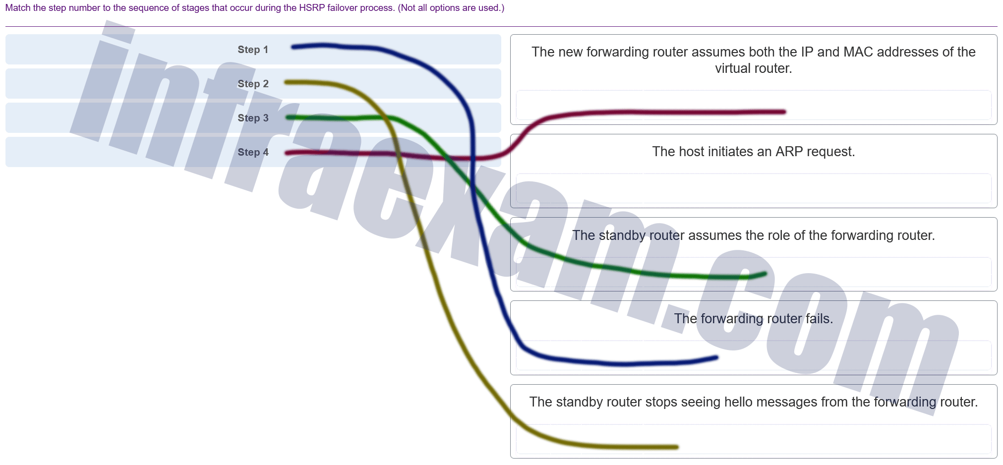
CCNA 2 SRWE v7 Modules 7 – 9 – Available and Reliable Networks Exam Answers 005 Answers Explanation & Hints: Hot Standby Router Protocol (HSRP) is a Cisco-proprietary protocol that is designed to allow for transparent failover of a first-hop IPv4 device.
-
In which situation would a technician use the show interfaces switch command?
- to determine if remote access is enabled
- when an end device can reach local devices, but not remote devices
- to determine the MAC address of a directly attached network device on a particular interface
- when packets are being dropped from a particular directly attached host
Explanation: The show interfaces command is useful to detect media errors, to see if packets are being sent and received, and to determine if any runts, giants, CRCs, interface resets, or other errors have occurred. Problems with reachability to a remote network would likely be caused by a misconfigured default gateway or other routing issue, not a switch issue. The show mac address-table command shows the MAC address of a directly attached device.
-
Refer to the exhibit. If the IP addresses of the default gateway router and the DNS server are correct, what is the configuration problem?

CCNA 2 v7 SRWE Final Exam Answers 08 - The default-router and dns-server commands need to be configured with subnet masks.
- The DNS server and the default gateway router should be in the same subnet.
- The IP address of the DNS server is not contained in the excluded address list.
- The IP address of the default gateway router is not contained in the excluded address list.
Explanation: In this configuration, the excluded address list should include the address that is assigned to the default gateway router. So the command should be ip dhcp excluded-address 192.168.10.1 192.168.10.9.
-
Refer to the exhibit. A network administrator has added a new subnet to the network and needs hosts on that subnet to receive IPv4 addresses from the DHCPv4 server.
What two commands will allow hosts on the new subnet to receive addresses from the DHCP4 server? (Choose two.)
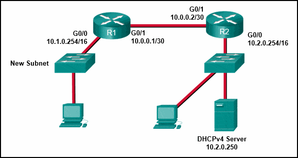
CCNA 2 v7 SRWE Final Exam Answers 19 - R2(config-if)# ip helper-address 10.2.0.250
- R1(config)# interface G0/1
- R1(config-if)# ip helper-address 10.2.0.250
- R1(config)# interface G0/0
- R1(config-if)# ip helper-address 10.1.0.254
- R2(config)# interface G0/0
-
Explanation & Hint: To enable hosts on the new subnet to receive IPv4 addresses from the DHCPv4 server, the network administrator needs to configure an IP Helper address on the router interface that is connected to the new subnet. The IP Helper address directs DHCP requests from hosts to the DHCP server located on a different subnet.
Based on the exhibit, the DHCP server has an IP address of 10.2.0.250 and is connected to R2. The new subnet is directly connected to R1’s G0/0 interface. Therefore, R1 needs to be configured to relay DHCP requests from the new subnet to the DHCP server.
The correct commands to accomplish this are:
- Enter the interface configuration mode for the interface connected to the new subnet:
R1(config)
- Configure the IP Helper address to point to the DHCP server’s IP address:
R1(config-if)
These commands tell R1 to forward DHCP requests that it receives on the G0/0 interface to the DHCP server at 10.2.0.250. DHCP requests are broadcast messages, and by default, routers do not forward broadcast messages across different subnets. The
ip helper-addresscommand enables the router to convert the broadcast to a unicast message to the specified IP address of the DHCP server, allowing the DHCP server to respond with an appropriate IP address lease for the host on the new subnet.Therefore, the two commands the administrator should use are:
R1(config)
R1(config-if) - Enter the interface configuration mode for the interface connected to the new subnet:
-
Refer to the exhibit. R1 has been configured as shown. However, PC1 is not able to receive an IPv4 address. What is the problem?
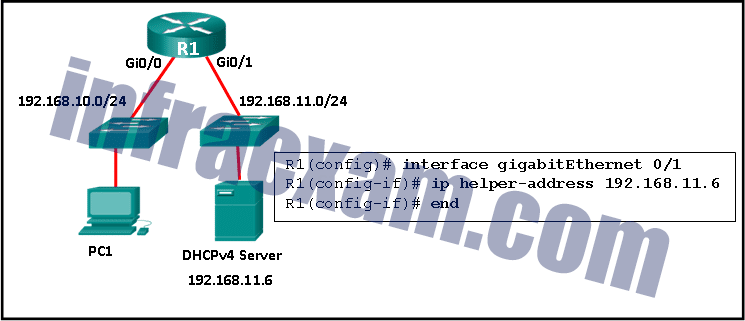
CCNA 2 v7 SRWE Final Exam Answers 09 - R1 is not configured as a DHCPv4 server.
- A DHCP server must be installed on the same LAN as the host that is receiving the IP address.
- The ip helper-address command was applied on the wrong interface.
- The ip address dhcp command was not issued on the interface Gi0/1.
Explanation: The ip helper-address command has to be applied on interface Gi0/0. This command must be present on the interface of the LAN that contains the DHCPv4 client PC1 and must be directed to the correct DHCPv4 server.
-
What network attack seeks to create a DoS for clients by preventing them from being able to obtain a DHCP lease?
- CAM table attack
- IP address spoofing
- DHCP spoofing
- DHCP starvation
Explanation: DCHP starvation attacks are launched by an attacker with the intent to create a DoS for DHCP clients. To accomplish this goal, the attacker uses a tool that sends many DHCPDISCOVER messages in order to lease the entire pool of available IP addresses, thus denying them to legitimate hosts.
-
A cybersecurity analyst is using the macof tool to evaluate configurations of switches deployed in the backbone network of an organization. Which type of LAN attack is the analyst targeting during this evaluation?
- VLAN double-tagging
- MAC address table overflow
- VLAN hopping
- DHCP spoofing
-
Explanation & Hint: The macof tool is used for MAC address table overflow attacks. This tool floods the switch with a large number of Ethernet frames, each with different MAC addresses. The goal is to overflow the switch’s MAC address table, causing the switch to enter a state where it behaves like a hub. This means the switch would start broadcasting all incoming packets to all ports because it cannot determine which port to send the packet to based on the MAC address. As a result, an attacker could potentially capture traffic not intended for their access, which could lead to information disclosure.
So, the type of LAN attack the analyst is targeting during this evaluation with the macof tool is MAC address table overflow.
-
Which information does a switch use to populate the MAC address table?
- the source MAC address and the incoming port
- the destination MAC address and the incoming port
- the source MAC address and the outgoing port
- the source and destination MAC addresses and the outgoing port
- the source and destination MAC addresses and the incoming port
- the destination MAC address and the outgoing port
Explanation: To maintain the MAC address table, the switch uses the source MAC address of the incoming packets and the port that the packets enter. The destination address is used to select the outgoing port.
-
Which statement describes a result after multiple Cisco LAN switches are interconnected?
- There is one broadcast domain and one collision domain per switch.
- The broadcast domain expands to all switches.
- One collision domain exists per switch.
- Frame collisions increase on the segments connecting the switches.
Explanation: In Cisco LAN switches, the microsegmentation makes it possible for each port to represent a separate segment and thus each switch port represents a separate collision domain. This fact will not change when multiple switches are interconnected. However, LAN switches do not filter broadcast frames. A broadcast frame is flooded to all ports. Interconnected switches form one big broadcast domain.
-
Match the forwarding characteristic to its type. (Not all options are used.)
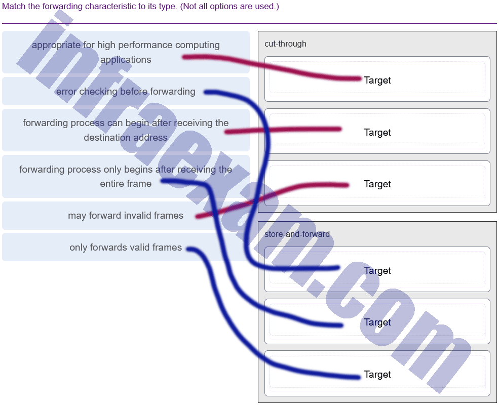
CCNA 2 v7 SRWE Final Exam Answers 005 -
Explanation & Hint:
-
-
Which method of IPv6 prefix assignment relies on the prefix contained in RA messages?
- EUI-64
- stateful DHCPv6
- static
- SLAAC
-
Explanation & Hint: The method of IPv6 prefix assignment that relies on the prefix contained in Router Advertisement (RA) messages is Stateless Address Autoconfiguration (SLAAC). When a host receives an RA message, it can automatically configure its own IPv6 address using the prefix advertised in the RA message along with its own interface identifier, which can be generated using the EUI-64 process or a random generator, depending on the host’s operating system and privacy settings.
SLAAC allows a device to create a globally unique address without the need for a DHCP server, although it can be used in conjunction with stateless DHCPv6 to obtain other configuration information like DNS servers.
-
On a Cisco 3504 WLC Summary page ( Advanced > Summary ), which tab allows a network administrator to configure a particular WLAN with a WPA2 policy?
- MANAGEMENT
- WLANs
- SECURITY
- WIRELESS
-
Explanation & Hint: On a Cisco Wireless LAN Controller (WLC) like the 3504, to configure a particular WLAN with a WPA2 policy, you would typically use the WLANs tab. Within this section, you can edit the settings for individual WLANs, including security policies such as WPA2.
Here’s a more detailed step on how you might do this:
- Click on the WLANs tab to view the list of WLANs.
- Select the specific WLAN you wish to configure.
- Within the WLAN settings, navigate to the Security tab (which is a sub-tab within the WLAN configuration).
- Choose the appropriate options for Layer 2 security, such as WPA2, and configure encryption and authentication settings as required.
So, while the WLANs tab is where you start the process, the actual security policy configuration (like setting WPA2) is done under the security settings for the specific WLAN you are configuring.
-
A network administrator of a small advertising company is configuring WLAN security by using the WPA2 PSK method. Which credential do office users need in order to connect their laptops to the WLAN?
- a key that matches the key on the AP
- a username and password configured on the AP
- a user passphrase
- the company username and password through Active Directory service
Explanation & Hint: When a WLAN is configured with WPA2 PSK, wireless users must know the pre-shared key to associate and authenticate with the AP.
-
What two default wireless router settings can affect network security? (Choose two.)

CCNA 2 v7 SRWE Final Exam Answers 15 - The SSID is broadcast.
- MAC address filtering is enabled.
- WEP encryption is enabled.
- The wireless channel is automatically selected.
- A well-known administrator password is set.
Explanation: Default settings on wireless routers often include broadcasting the SSID and using a well-known administrative password. Both of these pose a security risk to wireless networks. WEP encryption and MAC address filtering are not set by default. The automatic selection of the wireless channel poses no security risks.
-
Refer to the exhibit. Based on the exhibited configuration and output, why is VLAN 99 missing?
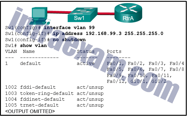
CCNA 2 v7 SRWE Final Exam Answers 21 - because there is a cabling problem on VLAN 99
- because VLAN 1 is up and there can only be one management VLAN on the switch
- because VLAN 99 has not yet been created
- because VLAN 99 is not a valid management VLAN
-
Explanation & Hint: Based on the configuration shown in the exhibit, VLAN 99 is missing from the VLAN brief output because it has not yet been created on the switch. The commands shown indicate that an interface for VLAN 99 has been configured with an IP address, and it has been brought up with the
no shutdowncommand. However, if VLAN 99 does not exist in the switch’s VLAN database, it will not appear in the VLAN brief output, even if an SVI (Switched Virtual Interface) for it has been configured.The correct action to resolve this issue would be to create VLAN 99 on the switch with the command
vlan 99in global configuration mode. After creating the VLAN, it should appear in the VLAN brief output and function as expected, assuming there are no other issues.
-
Which three pairs of trunking modes will establish a functional trunk link between two Cisco switches? (Choose three.)
- access – trunk
- dynamic auto – dynamic auto
- dynamic desirable – dynamic desirable
- dynamic desirable – dynamic auto
- dynamic desirable – trunk
- access – dynamic auto
-
Explanation & Hint: To establish a functional trunk link between two Cisco switches, the ports on both ends must be compatible and correctly negotiate the trunking status. Here are the modes that can successfully form a trunk:
- Dynamic Desirable – Dynamic Desirable: Both sides actively attempt to negotiate a trunk link using DTP (Dynamic Trunking Protocol).
- Dynamic Desirable – Dynamic Auto: One side actively attempts to negotiate a trunk link, and the other side is willing to convert to a trunk link if the other side initiates negotiation.
- Dynamic Desirable – Trunk: One side actively attempts to negotiate, while the other side is set to trunk mode and will form a trunk link.
The other combinations you’ve mentioned would not result in a trunk being formed:
- Access – Trunk: This pairing does not form a trunk because one side is set to never trunk (access).
- Dynamic Auto – Dynamic Auto: Neither side actively attempts to initiate trunking, so they will not form a trunk unless the other side initiates it.
- Access – Dynamic Auto: The access mode side is set to never trunk, and the dynamic auto side will not initiate a trunk, so a trunk will not form.
Therefore, the three pairs that will establish a functional trunk link are:
- Dynamic Desirable – Dynamic Desirable
- Dynamic Desirable – Dynamic Auto
- Dynamic Desirable – Trunk
-
Which three steps should be taken before moving a Cisco switch to a new VTP management domain? (Choose three.)
- Reset the VTP counters to allow the switch to synchronize with the other switches in the domain.
- Download the VTP database from the VTP server in the new domain.
- Select the correct VTP mode and version.
- Reboot the switch.
- Configure the VTP server in the domain to recognize the BID of the new switch.
- Configure the switch with the name of the new management domain.
Explanation: When adding a new switch to a VTP domain, it is critical to configure the switch with a new domain name, the correct VTP mode, VTP version number, and password. A switch with a higher revision number can propagate invalid VLANs and erase valid VLANs thus preventing connectivity for multiple devices on the valid VLANs.
-
Select the three PAgP channel establishment modes. (Choose three.)
- active
- passive
- desirable
- on
- auto
- blocking
-
Explanation & Hint: PAgP (Port Aggregation Protocol) is a Cisco-proprietary protocol used to automatically aggregate multiple physical ports into a single logical link. There are three modes that can be configured on a Cisco switch port for the establishment of a PAgP EtherChannel:
- Desirable: In this mode, the interface actively attempts to negotiate a PAgP EtherChannel. It initiates negotiations with other ports by sending PAgP packets.
- Auto: This mode places an interface in a passive negotiating state. In this state, the interface responds to PAgP packets it receives but does not initiate PAgP negotiation.
- On: This mode forces the channel to be up without any PAgP negotiation. In essence, this is a manual configuration, and both ends of the EtherChannel must be set to ‘on’ for the link to be part of the EtherChannel.
The other modes mentioned are related to LACP (Link Aggregation Control Protocol), which is another protocol used for port channeling, not PAgP:
- Active and Passive are LACP modes, where ‘active’ means the port actively tries to form an LACP EtherChannel, and ‘passive’ waits for another port to request to form an LACP EtherChannel.
- Blocking is not a mode for EtherChannel; it is a state used in Spanning Tree Protocol to prevent loops by blocking redundant paths.
So the correct PAgP channel establishment modes are Desirable, Auto, and On.
-
Refer to the exhibit. Which static route command can be entered on R1 to forward traffic to the LAN connected to R2?
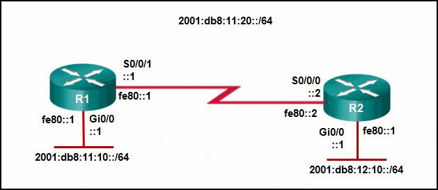
CCNA 2 v7 SRWE Final Exam Answers 11 - ipv6 route 2001:db8:12:10::/64 S0/0/0 fe80::2
- ipv6 route 2001:db8:12:10::/64 S0/0/1 fe80::2
- ipv6 route 2001:db8:12:10::/64 S0/0/1 2001:db8:12:10::1
- ipv6 route 2001:db8:12:10::/64 S0/0/0
-
Explanation & Hint: To configure a static route on R1 to forward traffic to the LAN connected to R2, you need to specify the destination network and the next-hop address. The next-hop address should be the link-local address of the interface on R2 that is directly reachable by R1.
According to the exhibit, the correct command should include the destination network
2001:db8:12:10::/64and the next-hop link-local addressfe80::2of R2’s interface that is directly connected to R1.However, you also need to specify the correct outgoing interface on R1 that faces R2. Based on the exhibit, the Serial interface S0/0/1 on R1 is connected to R2.
Therefore, the correct static route command to enter on R1 would be:
ipv6 route 2001:db8:12:10::/64 S0/0/1 fe80::2This command tells R1 to send packets destined for the
2001:db8:12:10::/64network to the next hop with the link-local addressfe80::2via its S0/0/1 interface.
-
Refer to the exhibit. R1 was configured with the static route command ip route 209.165.200.224 255.255.255.224 S0/0/0 and consequently users on network 172.16.0.0/16 are unable to reach resources on the Internet. How should this static route be changed to allow user traffic from the LAN to reach the Internet?
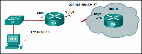
CCNA 2 v7 SRWE Final Exam Answers 18 - Add the next-hop neighbor address of 209.165.200.226.
- Change the destination network and mask to 0.0.0.0 0.0.0.0.
- Change the exit interface to S0/0/1.
- Add an administrative distance of 254.
Explanation: The static route on R1 has been incorrectly configured with the wrong destination network and mask. The correct destination network and mask is 0.0.0.0 0.0.0.0.
-
Refer to the exhibit. Currently router R1 uses an EIGRP route learned from Branch2 to reach the 10.10.0.0/16 network. Which floating static route would create a backup route to the 10.10.0.0/16 network in the event that the link between R1 and Branch2 goes down?
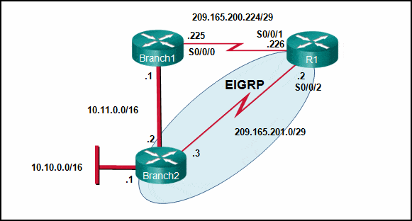
CCNA 2 v7 SRWE Final Exam Answers 16 - ip route 10.10.0.0 255.255.0.0 Serial 0/0/0 100
- ip route 10.10.0.0 255.255.0.0 209.165.200.226 100
- ip route 10.10.0.0 255.255.0.0 209.165.200.225 100
- ip route 10.10.0.0 255.255.0.0 209.165.200.225 50
Explanation: A floating static route needs to have an administrative distance that is greater than the administrative distance of the active route in the routing table. Router R1 is using an EIGRP route which has an administrative distance of 90 to reach the 10.10.0.0/16 network. To be a backup route the floating static route must have an administrative distance greater than 90 and have a next hop address corresponding to the serial interface IP address of Branch1.
-
Refer to the exhibit. A network engineer is configuring IPv6 routing on the network. Which command issued on router HQ will configure a default route to the Internet to forward packets to an IPv6 destination network that is not listed in the routing table?
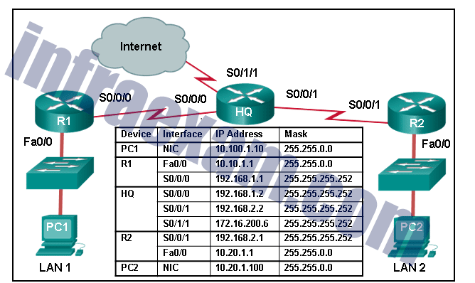
CCNA 2 v7 SRWE Final Exam Answers 06 - ipv6 route ::/0 serial 0/1/1
- ipv6 route ::1/0 serial 0/1/1
- ipv6 route ::/0 serial 0/0/0
- ip route 0.0.0.0 0.0.0.0 serial 0/1/1
-
Explanation & Hint: To configure a default route to the Internet for IPv6 traffic on router HQ, you would use the command that specifies the default route for IPv6 and the correct interface that leads to the Internet.
The correct command from the options provided would be:
ipv6 route ::/0 serial 0/1/1This command sets up a default route (represented by ::/0, which is the IPv6 equivalent of 0.0.0.0/0 in IPv4) that forwards all packets for unknown IPv6 destinations to the next hop interface of serial 0/1/1, which, according to the diagram, is the interface connected to the Internet.
The other commands have either incorrect syntax or pertain to IPv4 routing, which is not applicable when configuring IPv6 routing.
-
What protocol or technology uses a standby router to assume packet-forwarding responsibility if the active router fails?
- HSRP
- EtherChannel
- VTP
- DTP
-
Explanation & Hint: The protocol that uses a standby router to assume packet-forwarding responsibility if the active router fails is HSRP (Hot Standby Router Protocol). HSRP is a Cisco-proprietary redundancy protocol for establishing a fault-tolerant default gateway. It allows multiple routers to work together to present the appearance of a single virtual router or gateway to the hosts on the local network. If the currently active router fails, the standby router takes over the IP address and continues forwarding packets.
-
What is the effect of entering the ip arp inspection vlan 10 configuration command on a switch?
- It enables DHCP snooping globally on a switch.
- It specifies the maximum number of L2 addresses allowed on a port.
- It enables DAI on specific switch interfaces previously configured with DHCP snooping.
- It globally enables BPDU guard on all PortFast-enabled ports.
-
Explanation & Hint: The
ip arp inspection vlan 10command enables Dynamic ARP Inspection (DAI) for VLAN 10 on a switch. DAI is a security feature that checks ARP packets on the interfaces of a switch. It ensures that only valid ARP requests and responses are relayed. The switch checks the ARP packet against a trusted database of IP-to-MAC address bindings, which is usually built by DHCP snooping.DAI relies on DHCP snooping to build this database, so while DAI itself is not DHCP snooping, it works in conjunction with it. The other options listed do not accurately describe the effect of the
ip arp inspection vlancommand:- It enables DHCP snooping globally on a switch: This is incorrect because the command specified is for ARP inspection, not DHCP snooping.
- It specifies the maximum number of L2 addresses allowed on a port: This is more related to port security settings, not ARP inspection.
- It globally enables BPDU guard on all PortFast-enabled ports: This is incorrect because BPDU guard is related to Spanning Tree Protocol protection mechanisms, not ARP inspection.
Therefore, the correct effect of entering the
ip arp inspection vlan 10command is that it enables DAI for VLAN 10, which will check ARP packets against a trusted database to prevent ARP poisoning and spoofing attacks on that VLAN.
-
Refer to the exhibit. A network administrator is reviewing the configuration of switch S1. Which protocol has been implemented to group multiple physical ports into one logical link?
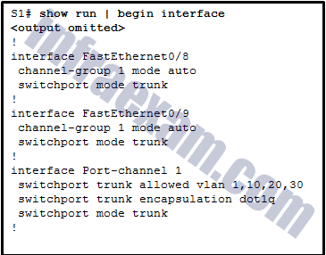
CCNA 2 v7 SRWE Final Exam Answers 12 - DTP
- LACP
- PAgP
- STP
-
Explanation & Hint: The configuration in the exhibit shows that the interfaces FastEthernet0/8 and FastEthernet0/9 on switch S1 have been configured with the
channel-group 1 mode autocommand. This command is used to configure the interfaces to negotiate an EtherChannel using Cisco’s Port Aggregation Protocol (PAgP).PAgP is a Cisco-proprietary protocol used in the automatic creation of a fast EtherChannel link. The
mode autocommand enables PAgP only if the other side is interested in forming a PAgP EtherChannel. Since this is a Cisco-specific feature and the command explicitly refers to a channel group, which is associated with port channels, the correct answer is PAgP.
-
Successful inter-VLAN routing has been operating on a network with multiple VLANs across multiple switches for some time. When an inter-switch trunk link fails and Spanning Tree Protocol brings up a backup trunk link, it is reported that hosts on two VLANs can access some, but not all the network resources that could be accessed previously. Hosts on all other VLANS do not have this problem. What is the most likely cause of this problem?
- The allowed VLANs on the backup link were not configured correctly.
- The protected edge port function on the backup trunk interfaces has been disabled.
- Dynamic Trunking Protocol on the link has failed.
- Inter-VLAN routing also failed when the trunk link failed.
-
Explanation & Hint: If the protected edge port function being disabled on the backup trunk interfaces is identified as the cause of the problem, this suggests a specific design in the network where the edge port protection plays a critical role in the accessibility of network resources.
Protected ports in a network are typically configured to isolate traffic between hosts on the same switch to prevent direct host-to-host communication. This is often used for security purposes. If these ports are part of the inter-VLAN routing process and they are disabled, it could potentially lead to a scenario where certain traffic types or flows expected to be isolated are now being transmitted or received in an unexpected manner, leading to the reported access issues.
In such a scenario, traffic that was once isolated might now be propagated due to the lack of protected port configuration, which could cause network resource accessibility issues due to potential security filters or policies being triggered by this unexpected traffic pattern.
To resolve this issue, the protected edge port function would need to be re-enabled on the backup trunk interfaces to restore the intended traffic flow and isolation as per the original network design. It’s also important to review the overall network design and understand why the protected port configuration is critical for resource access, as this is not a typical use case for protected ports.
-
Refer to the exhibit. An administrator is attempting to install an IPv6 static route on router R1 to reach the network attached to router R2. After the static route command is entered, connectivity to the network is still failing. What error has been made in the static route configuration?
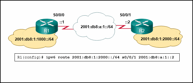
CCNA 2 v7 SRWE Final Exam Answers 23 - The interface is incorrect.
- The next hop address is incorrect.
- The network prefix is incorrect.
- The destination network is incorrect.
Answers Explanation & Hints: In this example the interface in the static route is incorrect. The interface should be the exit interface on R1, which is s0/0/0.
-
What protocol or technology uses source IP to destination IP as a load-balancing mechanism?
- EtherChannel
- VTP
- STP
- DTP
-
Explanation & Hint: The protocol or technology that uses source IP to destination IP as a load-balancing mechanism is EtherChannel. EtherChannel can use various load-balancing methods, and one common method involves hashing the source and destination IP addresses to determine which physical link within the EtherChannel to use for a particular packet. This way, the traffic between specific source and destination IP pairs can be consistently forwarded over the same physical link, which helps prevent out-of-order packet delivery. EtherChannel is a link aggregation technology that combines several physical links to create a single logical link for increased bandwidth and redundancy.
-
Refer to the exhibit. Router R1 has an OSPF neighbor relationship with the ISP router over the 192.168.0.32 network. The 192.168.0.36 network link should serve as a backup when the OSPF link goes down. The floating static route command ip route 0.0.0.0 0.0.0.0 S0/0/1 100 was issued on R1 and now traffic is using the backup link even when the OSPF link is up and functioning. Which change should be made to the static route command so that traffic will only use the OSPF link when it is up?
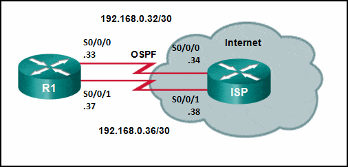
CCNA 2 v7 SRWE Final Exam Answers 24 - Change the administrative distance to 120.
- Change the administrative distance to 1.
- Add the next hop neighbor address of 192.168.0.36.
- Change the destination network to 192.168.0.34.
Answers Explanation & Hints: The problem with the current floating static route is that the administrative distance is set too low. The administrative distance will need to be higher than that of OSPF, which is 110, so that the router will only use the OSPF link when it is up.
-
Which type of static route is configured with a greater administrative distance to provide a backup route to a route learned from a dynamic routing protocol?
- standard static route
- default static route
- floating static route
- summary static route
Explanation: There are four basic types of static routes. Floating static routes are backup routes that are placed into the routing table if a primary route is lost. A summary static route aggregates several routes into one, reducing the of the routing table. Standard static routes are manually entered routes into the routing table. Default static routes create a gateway of last resort.
-
Which option shows a correctly configured IPv4 default static route?
- ip route 0.0.0.0 0.0.0.0 S0/0/0
- ip route 0.0.0.0 255.0.0.0 S0/0/0
- ip route 0.0.0.0 255.255.255.0 S0/0/0
- ip route 0.0.0.0 255.255.255.255 S0/0/0
Explanation: The static route ip route 0.0.0.0 0.0.0.0 S0/0/0 is considered a default static route and will match all destination networks.
-
Which command will start the process to bundle two physical interfaces to create an EtherChannel group via LACP?
- channel-group 2 mode auto
- channel-group 1 mode desirable
- interface port-channel 2
- interface range GigabitEthernet 0/4 – 5
Answers Explanation & Hints: To specify the interfaces in an EtherChannel group, use the interface range interface global configuration command for the range of interfaces used. The interface range GigabitEthernet 0/4 – 5 command is the correct option because it specifies two interfaces for the EtherChannel group.
-
What would be the primary reason an attacker would launch a MAC address overflow attack?
- so that the attacker can execute arbitrary code on the switch
- so that the switch stops forwarding traffic
- so that the attacker can see frames that are destined for other hosts
- so that legitimate hosts cannot obtain a MAC address
-
Explanation & Hint: The primary reason an attacker would launch a MAC address overflow attack is so that the attacker can see frames that are destined for other hosts. When the switch’s MAC address table becomes full, it can no longer associate new frames with specific ports. As a result, the switch behaves like a hub, broadcasting incoming frames to all ports, rather than forwarding them only to the correct destination port. This behavior allows an attacker to see traffic that is not intended for their host, effectively enabling the attacker to eavesdrop on the traffic traversing the switch. This type of attack is often used to capture sensitive data from other hosts on the network.
-
What is a method to launch a VLAN hopping attack?
- introducing a rogue switch and enabling trunking
- flooding the switch with MAC addresses
- sending spoofed IP addresses from the attacking host
- sending spoofed native VLAN information
-
Explanation & Hint: A VLAN hopping attack is where a device on one VLAN can receive traffic from another VLAN that it’s not a member of. One of the common methods to launch a VLAN hopping attack involves sending spoofed native VLAN information.
Here’s how the attack works using spoofed native VLAN information:
- An attacker configures a system to mimic a trunking interface by tagging Ethernet frames with the VLAN ID of the target VLAN.
- Because switches by default send traffic from the native VLAN untagged, the attacker sends frames with no VLAN tag.
- The switch receives these untagged frames and assumes they belong to the native VLAN.
- If the native VLAN of the attacker’s port matches the target VLAN, the switch forwards the frames to the target VLAN.
The attacker’s system essentially pretends to be a switch expecting untagged frames from the native VLAN, which the switch obligingly sends. This is a form of VLAN hopping because the traffic “hops” from the native VLAN to another without passing through a router.
Sending spoofed native VLAN information is a more direct and common method of VLAN hopping compared to the other options listed, which are:
- Introducing a rogue switch and enabling trunking: This could potentially allow VLAN hopping, but it involves physical access and more complex configuration.
- Flooding the switch with MAC addresses: This would lead to a different type of attack, such as a MAC address table overflow, which could make the switch act like a hub, broadcasting traffic to all ports.
- Sending spoofed IP addresses from the attacking host: This method would be more relevant to IP-based attacks, such as IP spoofing, rather than VLAN hopping.
-
Refer to the exhibit. All the displayed switches are Cisco 2960 switches with the same default priority and operating at the same bandwidth. Which three ports will be STP designated ports? (Choose three.)
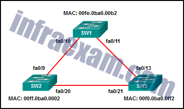
CCNA 2 v7 SRWE Final Exam Answers 25 - fa0/21
- fa0/10
- fa0/13
- fa0/9
- fa0/20
- fa0/11
-
Explanation & Hint: - fa0/21 (SW3): This is a designated port, which implies that SW3 has a lower path cost to the root bridge for that segment, or it could be that SW3 has a lower bridge ID than SW2 for that particular network segment.
- fa0/10 (SW1): This port being designated suggests that SW1 is the root bridge for the segment it shares with SW2 since it has a lower bridge ID, which in this case is determined by the MAC address.
- fa0/13 (SW3): For this port to be designated, it would mean that for the segment between SW1 and SW3, SW3 has the superior bridge ID (lower MAC address in this context) or a lower path cost to the root bridge, assuming all else is equal.
Given that all switches are said to have the same priority and bandwidth, the bridge ID (which consists of the priority and MAC address) would be the deciding factor here, assuming there are no other path cost differences.
It’s important to note that the actual selection of designated ports in an STP environment can be influenced by various factors beyond priority and MAC addresses, including port costs and port priorities, which are not visible in the information provided.
-
What is the common term given to SNMP log messages that are generated by network devices and sent to the SNMP server?
- traps
- auditing
- acknowledgments
- warnings
-
Explanation & Hint: The common term given to SNMP log messages that are generated by network devices and sent to the SNMP server is “traps”. In the context of SNMP (Simple Network Management Protocol), traps are automated notifications sent from an SNMP-enabled device to a management station or server, indicating a significant event or change in the device’s status.
-
A technician is troubleshooting a slow WLAN and decides to use the split-the-traffic approach. Which two parameters would have to be configured to do this? (Choose two.)
- Configure the 2.4 GHz band for basic internet traffic that is not time sensitive.
- Configure the security mode to WPA Personal TKIP/AES for both networks.
- Configure the security mode to WPA Personal TKIP/AES for one network and WPA2 Personal AES for the other network
- Configure a common SSID for both split networks.
- Configure the 5 GHz band for streaming multimedia and time sensitive traffic.
-
Explanation & Hint: To implement a split-the-traffic approach in a wireless LAN (WLAN), you would need to configure the following parameters:
- Configure the 2.4 GHz band for basic internet traffic that is not time-sensitive.
- This involves setting up a wireless network (SSID) on the 2.4 GHz band with appropriate security settings and possibly quality of service (QoS) policies to prioritize internet traffic that is not time-sensitive, such as general web browsing.
- Configure the 5 GHz band for streaming multimedia and time-sensitive traffic.
- On the 5 GHz band, you would set up a separate wireless network (SSID) with the necessary security settings and QoS policies to prioritize time-sensitive traffic like streaming multimedia, voice, or video conferencing. The 5 GHz band is often preferred for time-sensitive applications due to its higher throughput and less interference.
The other options listed are not directly related to implementing the split-the-traffic approach:
- Configure the security mode to WPA Personal TKIP/AES for both networks: This relates to the security settings of the WLANs but does not specify how traffic should be split based on usage.
- Configure the security mode to WPA Personal TKIP/AES for one network and WPA2 Personal AES for the other network: Again, this relates to security settings but does not address the split-traffic approach.
- Configure a common SSID for both split networks: A common SSID would not achieve the goal of splitting traffic based on its characteristics; it would provide access to both networks using the same SSID.
- Configure the 2.4 GHz band for basic internet traffic that is not time-sensitive.
-
A company security policy requires that all MAC addressing be dynamically learned and added to both the MAC address table and the running configuration on each switch. Which port security configuration will accomplish this?
- auto secure MAC addresses
- dynamic secure MAC addresses
- static secure MAC addresses
- sticky secure MAC addresses
Answers Explanation & Hints: With sticky secure MAC addressing, the MAC addresses can be either dynamically learned or manually configured and then stored in the address table and added to the running configuration file. In contrast, dynamic secure MAC addressing provides for dynamically learned MAC addressing that is stored only in the address table.
-
What is the IPv6 prefix that is used for link-local addresses?
- FE80::/10
- FF01::/8
- FC00::/7
- 2001::/3
-
Explanation & Hint: The IPv6 prefix used for link-local addresses is
FE80::/10. These addresses are automatically configured on all IPv6-enabled interfaces and can be used for communication on the local link only. They are not routable beyond the link (subnet) that a host is connected to.
-
What action takes place when a frame entering a switch has a unicast destination MAC address that is not in the MAC address table?
- The switch resets the refresh timer on all MAC address table entries.
- The switch updates the refresh timer for the entry.
- The switch replaces the old entry and uses the more current port.
- The switch will forward the frame out all ports except the incoming port.
-
Explanation & Hint: When a frame entering a switch has a unicast destination MAC address that is not in the MAC address table, the switch will:
The switch will forward the frame out all ports except the incoming port.
This behavior is known as “flooding.” The switch does this because it does not have any information on which port the destination device is located. By flooding the frame to all ports (except the one it received the frame on), the switch ensures that the frame reaches its intended destination. Once the destination device responds and the switch receives a frame with the source MAC address of that device, the switch will then add the MAC address and corresponding port to the MAC address table for future reference.
-
A new switch is to be added to an existing network in a remote office. The network administrator does not want the technicians in the remote office to be able to add new VLANs to the switch, but the switch should receive VLAN updates from the VTP domain. Which two steps must be performed to configure VTP on the new switch to meet these conditions? (Choose two.)
- Configure the existing VTP domain name on the new switch.
- Configure all ports of both switches to access mode.
- Enable VTP pruning.
- Configure an IP address on the new switch.
- Configure the new switch as a VTP client.
-
Explanation & Hint: To ensure the new switch receives VLAN updates from the VTP domain but does not allow technicians to add new VLANs, the network administrator should:
- Configure the existing VTP domain name on the new switch.
- This step is essential for the new switch to participate in the VTP domain and receive VLAN updates from the VTP server.
- Configure the new switch as a VTP client.
- Setting the switch to VTP client mode will ensure that it receives updates from the VTP server but cannot create, modify, or delete VLANs. The technicians will not be able to add new VLANs in this mode.
The other options listed are not directly related to controlling VLAN updates via VTP:
- Configure all ports of both switches to access mode: This step would not affect VTP configurations or the ability to receive VLAN updates. It would just ensure that all ports belong to a single VLAN and do not carry traffic for multiple VLANs.
- Enable VTP pruning: VTP pruning is used to increase network available bandwidth by restricting flooded traffic to those trunk links that the traffic must use to access the appropriate network devices. It is not related to the requirement of preventing the addition of new VLANs.
- Configure an IP address on the new switch: Providing an IP address to a switch is usually for management purposes and does not directly affect VTP operation. VTP operates on a Layer 2 level, using VLAN trunking.
- Configure the existing VTP domain name on the new switch.
-
Refer to the exhibit. Which three hosts will receive ARP requests from host A, assuming that port Fa0/4 on both switches is configured to carry traffic for multiple VLANs? (Choose three.)
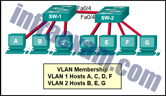
CCNA 2 v7 SRWE Final Exam Answers 27 - host F
- host B
- host D
- host G
- host C
- host E
Explanation: ARP requests are sent out as broadcasts. That means the ARP request is sent only throughout a specific VLAN. VLAN 1 hosts will only hear ARP requests from hosts on VLAN 1. VLAN 2 hosts will only hear ARP requests from hosts on VLAN 2.
-
A technician is configuring a router for a small company with multiple WLANs and doesn’t need the complexity of a dynamic routing protocol. What should be done or checked?
- Check the configuration on the floating static route and adjust the AD.
- Create a floating static route to that network.
- Verify that there is not a default route in any of the edge router routing tables.
- Create static routes to all internal networks and a default route to the internet.
-
Explanation & Hint: For a small company with multiple WLANs that does not require the complexity of a dynamic routing protocol, the technician should:
Create static routes to all internal networks and a default route to the internet.
Static routing is a simple way to ensure that data can reach its destination without the need for a routing protocol. The technician would specify a fixed path in the router’s configuration for each network. Additionally, a default route (often referred to as the “gateway of last resort”) should be configured to direct any traffic destined for unknown networks (typically the internet) to the next hop router or directly to the company’s internet service provider.
The other options listed are less relevant to the scenario described:
- Check the configuration on the floating static route and adjust the AD: Floating static routes are typically used as backup routes and have a higher Administrative Distance (AD) than the primary route. This would not be necessary unless there is a requirement for a backup route to a particular network.
- Create a floating static route to that network: A floating static route is not the primary route and would only be used if the primary route fails, which is not the typical requirement for a basic setup.
- Verify that there is not a default route in any of the edge router routing tables: It’s actually necessary to ensure that there is a default route in the routing table to handle traffic to external networks. This option seems to be the opposite of what should be done.
-
Which two functions are performed by a WLC when using split media access control (MAC)? (Choose two.)
- packet acknowledgments and retransmissions
- frame translation to other protocols
- association and re-association of roaming clients
- beacons and probe responses
- frame queuing and packet prioritization
-
Explanation & Hint: In a wireless network architecture that uses a Wireless LAN Controller (WLC) with split MAC operations, certain functions are handled by the WLC and others are handled by the lightweight access points (APs). When using split MAC, the WLC performs the following functions:
- Association and Re-association of Roaming Clients:
- The WLC manages client associations and re-associations, especially when clients roam between different APs. The WLC ensures that clients have a seamless roaming experience by managing their credentials and maintaining their session as they move.
- Frame Queuing and Packet Prioritization:
- The WLC is responsible for managing queues for handling data frames and prioritizing packets. This includes implementing Quality of Service (QoS) policies to prioritize traffic, such as voice over IP (VoIP) over regular data traffic.
The other functions listed are typically performed by the lightweight APs in a split MAC architecture:
- Packet Acknowledgments and Retransmissions:
- The AP handles acknowledgments of packets and retransmissions at the MAC layer due to its proximity to the client devices and the need for immediate response to maintain efficient communication.
- Beacons and Probe Responses:
- Beacons and probe responses are used to announce the presence of a wireless network and respond to clients scanning for networks. These are transmitted directly by the APs.
- Frame Translation to Other Protocols:
- While not typically described as a function of split MAC architecture, frame translation or encapsulation may occur within the network infrastructure, but it is not a primary function associated with split MAC operations in a wireless context.
- Association and Re-association of Roaming Clients:
-
Refer to the exhibit. A network administrator configured routers R1 and R2 as part of HSRP group 1. After the routers have been reloaded, a user on Host1 complained of lack of connectivity to the Internet The network administrator issued the show standby brief command on both routers to verify the HSRP operations. In addition, the administrator observed the ARP table on Host1. Which entry should be seen in the ARP table on Host1 in order to gain connectivity to the Internet?
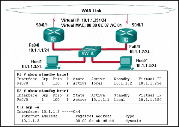
CCNA 2 v7 SRWE Final Exam Answers 28 - the IP address and the MAC address of R1
- the virtual IP address of the HSRP group 1 and the MAC address of R1
- the virtual IP address of the HSRP group 1 and the MAC address of R2
- the virtual IP address and the virtual MAC address for the HSRP group 1
Explanation: Hosts will send an ARP request to the default gateway which is the virtual IP address. ARP replies from the HSRP routers contain the virtual MAC address. The host ARP tables will contain a mapping of the virtual IP to the virtual MAC.
-
A network administrator is configuring a new Cisco switch for remote management access. Which three items must be configured on the switch for the task? (Choose three.)
- IP address
- default gateway
- default VLAN
- vty lines
- VTP domain
- loopback address
Explanation: To enable the remote management access, the Cisco switch must be configured with an IP address and a default gateway. In addition, vty lines must configured to enable either Telnet or SSH connections. A loopback address, default VLAN, and VTP domain configurations are not necessary for the purpose of remote switch management.
-
Refer to the exhibit. What can be concluded about the configuration shown on R1?
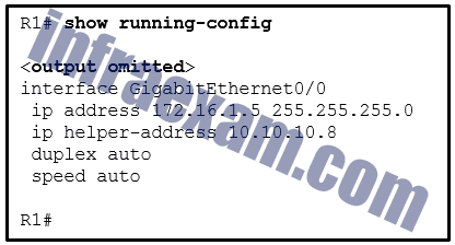
CCNA 2 v7 SRWE Final Exam Answers 26 - R1 is configured as a DHCPv4 relay agent.
- R1 will send a message to a local DHCPv4 client to contact a DHCPv4 server at 10.10.10.8.
- R1 will broadcast DHCPv4 requests on behalf of local DHCPv4 clients.
- R1 is operating as a DHCPv4 server.
-
Explanation & Hint: The configuration shown on R1 includes the
ip helper-address 10.10.10.8command on the GigabitEthernet0/0 interface. This configuration indicates that R1 is set up as a DHCPv4 relay agent. The role of a DHCP relay agent is to forward DHCP requests received on one interface to a DHCP server located on a different network. In this case, DHCP requests received on the GigabitEthernet0/0 interface will be forwarded to the DHCP server at the IP address 10.10.10.8.Here are the conclusions related to the exhibit:
- R1 is configured as a DHCPv4 relay agent. This is the correct conclusion based on the
ip helper-addresscommand.
The
ip helper-addresscommand does not cause R1 to send messages directly to DHCP clients, broadcast DHCP requests, or operate as a DHCP server itself. The purpose of the command is to relay requests to the specified server address. - R1 is configured as a DHCPv4 relay agent. This is the correct conclusion based on the
-
What action does a DHCPv4 client take if it receives more than one DHCPOFFER from multiple DHCP servers?
- It sends a DHCPREQUEST that identifies which lease offer the client is accepting.
- It sends a DHCPNAK and begins the DHCP process over again.
- It accepts both DHCPOFFER messages and sends a DHCPACK.
- It discards both offers and sends a new DHCPDISCOVER.
-
Explanation & Hint: When a DHCPv4 client receives more than one DHCPOFFER from multiple DHCP servers, it will choose one offer based on its own selection criteria (which could be the first offer received or the best offer based on certain metrics such as lease time or server preference). The client then sends a DHCPREQUEST message back to the network to identify which lease offer it is accepting. This request is broadcast to all DHCP servers to let any other servers that might have made offers know that their offer is not being accepted. The server whose offer was accepted will respond with a DHCPACK, completing the process.
-
What protocol should be disabled to help mitigate VLAN attacks?
- STP
- CDP
- DTP
- ARP
-
Explanation & Hint: To help mitigate VLAN attacks, you should disable DTP (Dynamic Trunking Protocol). DTP can be used by an attacker to negotiate a trunk link with a switch, which can allow them to access all VLANs across that trunk. Disabling DTP on switch ports that do not need to form trunks is a best practice for VLAN security.
While STP (Spanning Tree Protocol) and CDP (Cisco Discovery Protocol) have their own associated security risks, they are not specifically used to mitigate VLAN attacks. ARP (Address Resolution Protocol) is unrelated to VLAN security specifically and is necessary for IPv4 communication within a network.
-
Why is DHCP snooping required when using the Dynamic ARP Inspection feature?
- It uses the MAC address table to verify the default gateway IP address.
- It redirects ARP requests to the DHCP server for verification.
- It relies on the settings of trusted and untrusted ports set by DHCP snooping.
- It uses the MAC-address-to-IP-address binding database to validate an ARP packet.
Explanation: DAI relies on DHCP snooping. DHCP snooping listens to DHCP message exchanges and builds a bindings database of valid tuples (MAC address, IP address, VLAN interface).
When DAI is enabled, the switch drops ARP packet if the sender MAC address and sender IP address do not match an entry in the DHCP snooping bindings database. However, it can be overcome through static mappings. Static mappings are useful when hosts configure static IP addresses, DHCP snooping cannot be run, or other switches in the network do not run dynamic ARP inspection. A static mapping associates an IP address to a MAC address on a VLAN.
-
To obtain an overview of the spanning tree status of a switched network, a network engineer issues the show spanning-tree command on a switch. Which two items of information will this command display? (Choose two.)
- The role of the ports in all VLANs.
- The root bridge BID.
- The number of broadcasts received on each root port.
- The IP address of the management VLAN interface.
- The status of native VLAN ports.
-
Explanation & Hint: The
show spanning-treecommand on a Cisco switch provides detailed information about the Spanning Tree Protocol (STP) status for all VLANs that are present and active on the switch. This includes:- The role of the ports in all VLANs.
- This command will display the role of each port, such as whether it is a root port (RP), designated port (DP), alternate port (Altn), or a blocked port (Blk) in the STP topology.
- The root bridge BID (Bridge ID).
- The output will show the Bridge ID of the root bridge for each VLAN, which includes the priority and the MAC address. It also shows the switch’s own Bridge ID and how it compares to the root.
The
show spanning-treecommand does not provide the number of broadcasts received on each root port, the IP address of the management VLAN interface, or the status of the native VLAN ports specifically. The command focuses on STP state, port roles, port states (Forwarding or Blocking), path costs, and STP timers. It might show the state of ports in the native VLAN in the context of their STP roles and states, but it does not give specific status information pertaining only to the native VLAN. - The role of the ports in all VLANs.
-
A WLAN engineer deploys a WLC and five wireless APs using the CAPWAP protocol with the DTLS feature to secure the control plane of the network devices. While testing the wireless network, the WLAN engineer notices that data traffic is being exchanged between the WLC and the APs in plain-text and is not being encrypted. What is the most likely reason for this?
- DTLS only provides data security through authentication and does not provide encryption for data moving between a wireless LAN controller (WLC) and an access point (AP).
- Data encryption requires a DTLS license to be installed on each access point (AP) prior to being enabled on the wireless LAN controller (WLC).
- Although DTLS is enabled by default to secure the CAPWAP control channel, it is disabled by default for the data channel.
- DTLS is a protocol that only provides security between the access point (AP) and the wireless client.
Explanation: DTLS is a protocol which provides security between the AP and the WLC. It allows them to communicate using encryption and prevents eavesdropping or tampering.
DTLS is enabled by default to secure the CAPWAP control channel but is disabled by default for the data channel. All CAPWAP management and control traffic exchanged between an AP and WLC is encrypted and secured by default to provide control plane privacy and prevent Man-In-the-Middle (MITM) attacks.
-
Refer to the exhibit. The network administrator configures both switches as displayed. However, host C is unable to ping host D and host E is unable to ping host F. What action should the administrator take to enable this communication?
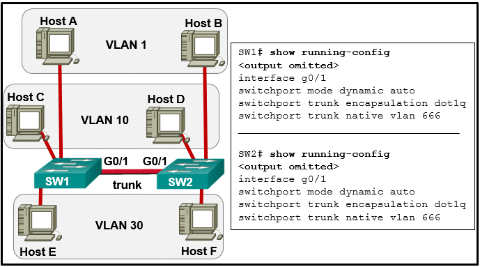
CCNA 2 v7 SRWE Final Exam Answers 29 - Associate hosts A and B with VLAN 10 instead of VLAN 1.
- Configure either trunk port in the dynamic desirable mode.
- Add the switchport nonegotiate command to the configuration of SW2.
- Include a router in the topology.
- Remove the native VLAN from the trunk.
-
Explanation & Hint: The exhibit shows the configuration of the trunk links between two switches, SW1 and SW2. Both switches have their trunk ports set to “dynamic auto” mode and are using VLAN 666 as the native VLAN. Hosts C and D are on VLAN 10, while Hosts E and F are on VLAN 30. Since Host C is unable to ping Host D and Host E is unable to ping Host F, there appears to be an issue with VLANs communication across the trunk link.
Here are the potential issues and the actions that could resolve the communication problems:
- Mismatched Trunk Negotiation Modes:
- With both interfaces set to “dynamic auto,” neither switch is actively attempting to form a trunk, which can result in the link not forming a trunk at all. The solution would be to set at least one side to “dynamic desirable” to actively attempt to form a trunk, which is necessary for the VLANs to communicate across the switches.
- Native VLAN Mismatch:
- If there is a native VLAN mismatch and VLAN 666 is not used on both ends of the trunk or by the hosts, it could cause traffic from the native VLAN to be untagged and not understood on the opposite switch. However, the configuration shows the same native VLAN, so this is not likely the issue.
- VLANs not allowed on the trunk:
- The configurations provided do not show the ‘switchport trunk allowed vlan’ command. If VLANs 10 and 30 are not explicitly allowed on the trunk, this would prevent traffic from those VLANs from crossing the trunk. The administrator should ensure that all necessary VLANs are allowed on the trunk.
- No switchport nonegotiate:
- The ‘switchport nonegotiate’ command prevents DTP (Dynamic Trunking Protocol) frames from being sent out of the port. However, if both sides are set to dynamic auto and the link is not establishing as a trunk, it’s not a negotiation issue. This command would be more relevant if one end of the trunk were set to a non-negotiable mode, like static access or trunk, and you wanted to prevent DTP frames from being sent.
Based on the output and the possible issues, the action that the administrator should take to enable communication between Host C and Host D as well as Host E and Host F is likely:
Configure either trunk port in the dynamic desirable mode.
This will actively attempt to form a trunk. It is important to note that “dynamic auto” mode will not form a trunk unless the other end is in “dynamic desirable” or “trunk” mode. Setting one end to “dynamic desirable” will initiate trunking and allow traffic from VLANs 10 and 30 to pass through.
- Mismatched Trunk Negotiation Modes:
-
What action takes place when the source MAC address of a frame entering a switch is not in the MAC address table?
- The switch replaces the old entry and uses the more current port.
- The switch adds a MAC address table entry for the destination MAC address and the egress port.
- The switch updates the refresh timer for the entry.
- The switch adds the MAC address and incoming port number to the table.
-
Explanation & Hint: When a switch receives a frame and the source MAC address of that frame is not in the MAC address table, the switch will:
The switch adds the MAC address and incoming port number to the table.
This is how a switch learns the locations of devices within the network. Each time a frame is received, the switch records the source MAC address and the port on which the frame arrived. If a frame arrives with a destination MAC address that is not known, the switch will broadcast the frame out of all ports except the one on which it was received. However, it does not add the destination MAC address to the table until it receives a frame originating from that MAC address.
-
A technician is configuring a wireless network for a small business using a SOHO wireless router. Which two authentication methods are used, if the router is configured with WPA2? (Choose two.) **
- AES
- TKIP
- personal
- WEP
- enterprise
-
Explanation & Hint: When configuring a wireless network with WPA2 on a SOHO router, the two authentication methods associated with WPA2 are:
- AES (Advanced Encryption Standard): WPA2 uses AES for encryption, which provides strong security.
- Personal or Enterprise:
- Personal (also known as WPA2-PSK for Pre-Shared Key): This is used in smaller networks where each user is given the same passphrase to connect.
- Enterprise (also known as WPA2-802.1X): This is used in larger businesses where an authentication server authenticates each user individually, often through a RADIUS server.
TKIP is an older encryption protocol associated with the original WPA standard, not WPA2, due to its vulnerabilities.
WEP is an outdated and insecure protocol that was used before WPA and is not used in conjunction with WPA2.
-
A network administrator is adding a new WLAN on a Cisco 3500 series WLC. Which tab should the administrator use to create a new VLAN interface to be used for the new WLAN?
- WLANs
- CONTROLLER
- WIRELESS
- MANAGEMENT
-
Explanation & Hint: On a Cisco 3500 series Wireless LAN Controller (WLC), to create a new VLAN interface that will be used for a new WLAN, the network administrator should use the CONTROLLER tab. This is where you can define dynamic interfaces, which are used to map VLANs to WLANs. Dynamic interfaces serve as the link between the wireless clients on the WLAN and the wired network infrastructure. After creating the VLAN interface, the administrator can then associate it with a WLAN under the WLANs tab.
-
Refer to the exhibit. Which two conclusions can be drawn from the output? (Choose two.)
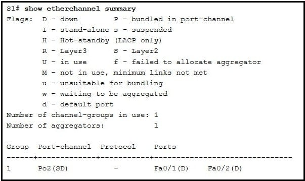
CCNA 2 v7 SRWE Final Exam Answers 30 - The port channel ID is 2.
- The bundle is fully operational.
- The port channel is a Layer 3 channel.
- The load-balancing method used is source port to destination port.
- The EtherChannel is down.
-
Explanation & Hint: Based on the output from the
show etherchannel summarycommand in the exhibit, the following two conclusions can be drawn:- The port channel ID is 2.
- The output shows “Group 1” and “Po2” which indicates the port-channel interface ID is 2. The number after “Po” typically represents the port-channel ID.
- The EtherChannel is down.
- Both ports Fa0/1 and Fa0/2 have the flag “(D)” next to them, which, according to the flag legend in the output, stands for “down”. Additionally, the port-channel Po2 also has an “(SD)” flag, with “S” meaning “layer2” (which by itself doesn’t indicate a down state), but “D” meaning “down”. The combination indicates that the EtherChannel is not currently operational.
The output does not provide enough information to conclude that the port channel is a Layer 3 channel or what load-balancing method is used, and the fact that the EtherChannel is down precludes it from being fully operational.
- The port channel ID is 2.
-
Which three statements accurately describe duplex and speed settings on Cisco 2960 switches? (Choose three.)
- By default, the speed is set to 100 Mb/s and the duplex mode is set to autonegotiation.
- An autonegotiation failure can result in connectivity issues.
- The duplex and speed settings of each switch port can be manually configured.
- When the speed is set to 1000 Mb/s, the switch ports will operate in full-duplex mode.
- By default, the autonegotiation feature is disabled.
- Enabling autonegotiation on a hub will prevent mismatched port speeds when connecting the hub to the switch.
-
Explanation & Hint:
-
Refer to the exhibit. A Layer 3 switch routes for three VLANs and connects to a router for Internet connectivity. Which two configurations would be applied to the switch? (Choose two.)
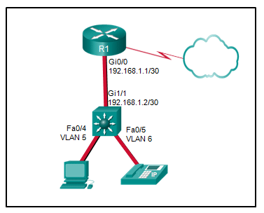
CCNA 2 v7 SRWE Final Exam Answers 31 - (config)# interface fastethernet0/4
(config-if)# switchport mode trunk - (config)# interface vlan 1
(config-if)# ip address 192.168.1.2 255.255.255.0
(config-if)# no shutdown - (config)# ip routing
- (config)# interface gigabitethernet 1/1
(config-if)# no switchport
(config-if)# ip address 192.168.1.2 255.255.255.252 - (config)# interface gigabitethernet1/1
(config-if)# switchport mode trunk -
Explanation & Hint: Based on the exhibit, which shows a Layer 3 switch that routes for three VLANs and has a connection to a router for Internet connectivity, the following configurations would be applied to the switch
- Enable IP Routing:
- Since the switch is performing Layer 3 routing for the VLANs, the
ip routingcommand would be used to enable the routing functionality on the switch.
(config)# ip routing
- Since the switch is performing Layer 3 routing for the VLANs, the
- Configure the Interface Connected to the Router:
- The interface Gi1/1 on the switch that connects to the router should have an IP address that is in the same subnet as the router interface it is connected to. Since the router’s interface is configured with the IP address 192.168.1.1/30, the switch interface Gi1/1 would need an IP address in the same subnet, but not the same IP. The next available IP in this subnet would typically be 192.168.1.2/30.
(config)# interface gigabitethernet 1/1
(config-if)# no switchport
(config-if)# ip address 192.168.1.2 255.255.255.252
- The interface Gi1/1 on the switch that connects to the router should have an IP address that is in the same subnet as the router interface it is connected to. Since the router’s interface is configured with the IP address 192.168.1.1/30, the switch interface Gi1/1 would need an IP address in the same subnet, but not the same IP. The next available IP in this subnet would typically be 192.168.1.2/30.
The first configuration snippet sets the FastEthernet 0/4 interface to trunk mode, which is not consistent with the exhibit since Fa0/4 is associated with VLAN 5, and should not be a trunk if it’s used to connect to an end device like a PC.
The second configuration snippet assigns an IP address to VLAN 1, which would not be necessary if VLAN 1 is not used for routing on the switch, and the IP addressing scheme doesn’t fit with the given subnet mask for the VLAN interfaces shown in the exhibit.
The last snippet is setting the GigabitEthernet 1/1 interface to trunk mode, which is not correct because this interface should be configured with an IP address for Layer 3 connectivity to the router, as shown in the correct configuration snippet above.
- Enable IP Routing:
- (config)# interface fastethernet0/4
-
Refer to the exhibit. Consider that the main power has just been restored. PC3 issues a broadcast IPv4 DHCP request. To which port will SW1 forward this request?
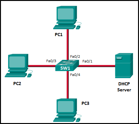
CCNA 2 v7 SRWE Final Exam Answers 32 - to Fa0/1 only
- to Fa0/1, Fa0/2, and Fa0/4 only
- to Fa0/1, Fa0/2, Fa0/3, and Fa0/4
- to Fa0/1, Fa0/2, and Fa0/3 only
- to Fa0/1 and Fa0/2 only
-
Explanation & Hint: Fa0/4 is the incoming port where PC3, which issued the DHCP request, is connected, then the switch will forward the broadcast DHCP request out of all its other active ports except for Fa0/4. This ensures that the request can reach the DHCP server and any other device that needs to hear the broadcast within the VLAN.
Given this information, the correct ports that SW1 will forward the DHCP request to are:
- Fa0/1, where the DHCP server is connected
- Fa0/2, where PC1 is connected
- Fa0/3, where PC2 is connected
The switch will not forward the broadcast to Fa0/4 because that’s the port from which the request originated.
Therefore, the correct answer is: to Fa0/1, Fa0/2, and Fa0/3 only
-
Which statement is correct about how a Layer 2 switch determines how to forward frames?
- Only frames with a broadcast destination address are forwarded out all active switch ports.
- Frame forwarding decisions are based on MAC address and port mappings in the CAM table.
- Cut-through frame forwarding ensures that invalid frames are always dropped.
- Unicast frames are always forwarded regardless of the destination MAC address.
Explanation: Cut-through frame forwarding reads up to only the first 22 bytes of a frame, which excludes the frame check sequence and thus invalid frames may be forwarded. In addition to broadcast frames, frames with a destination MAC address that is not in the CAM are also flooded out all active ports. Unicast frames are not always forwarded. Received frames with a destination MAC address that is associated with the switch port on which it is received are not forwarded because the destination exists on the network segment connected to that port.
-
Employees are unable to connect to servers on one of the internal networks. What should be done or checked?
- Use the “show ip interface brief” command to see if an interface is down.
- Verify that there is not a default route in any of the edge router routing tables.
- Check the statistics on the default route for oversaturation.
- Create static routes to all internal networks and a default route to the internet.
-
Explanation & Hint: When employees are unable to connect to servers on one of the internal networks, several steps should be taken to diagnose and resolve the issue:
- Use the “show ip interface brief” Command:
- This command will display the status of all interfaces on a router or switch. Check for any interfaces that are down, particularly those that should be connected to the affected network. An interface in a down state could indicate a physical connectivity issue, such as a disconnected cable or a hardware failure.
- Verify the Routing Table:
- Ensure that the correct routes are present in the routing table of the routers. This includes checking for specific routes to the internal network where the servers reside.
- If a route to the internal network is missing, packets destined for that network might be incorrectly routed or dropped.
- Check the Default Route:
- Verify the presence and correctness of a default route in the routing tables, especially if the issue is with external connectivity. However, if the problem is solely with accessing internal servers, the default route may be less likely to be the issue.
- Checking the statistics on the default route for oversaturation is also a good practice. If the default route is oversaturated, it could lead to performance issues, but this is more relevant for internet-bound traffic rather than internal network traffic.
- Review Access Control Lists (ACLs) and Firewall Rules:
- Check if any ACLs or firewall rules are blocking the traffic to the servers. Sometimes, changes in these configurations can inadvertently block legitimate traffic.
- Network Health and Performance:
- Look for signs of network congestion, oversaturation, or equipment issues that might be affecting traffic flow to the servers.
- Physical Connectivity and Network Hardware:
- Verify physical connectivity. Ensure that cables, switches, and routers that connect to the affected servers are functioning correctly.
- Create Static Routes to Internal Networks (if necessary):
- If dynamic routing is not properly distributing routes, or in a smaller network where dynamic routing might not be implemented, creating static routes to internal networks can ensure proper routing. However, this is typically considered when a new network segment is added or when changes are made to the network structure.
Given these options, the most immediate and relevant action would be to use the “show ip interface brief” command to check the status of the interfaces. This could quickly reveal if there is a straightforward connectivity issue. Subsequent steps would involve deeper investigation into routing and network configurations.
- Use the “show ip interface brief” Command:
-
What protocol or technology requires switches to be in server mode or client mode?
- VTP
- EtherChannel
- HSRP
- DTP
-
Explanation & Hint: The protocol or technology that requires switches to be in server mode or client mode is VTP, which stands for VLAN Trunking Protocol. VTP is a Cisco-proprietary protocol used for managing VLAN information on a network of switches. In VTP, switches can be configured in one of three modes:
- Server Mode: In this mode, switches can create, modify, and delete VLANs. Changes made on a server are advertised to the entire VTP domain.
- Client Mode: Switches in client mode cannot create, change, or delete VLANs. They only receive information from VTP servers and update their VLAN configuration accordingly.
- Transparent Mode: This is the third mode, where switches do not participate in the VTP domain but will forward VTP advertisements through their trunk ports.
EtherChannel, HSRP (Hot Standby Router Protocol), and DTP (Dynamic Trunking Protocol) do not use server or client modes in their configurations. EtherChannel is a link aggregation technology, HSRP is a network redundancy protocol, and DTP is a protocol used for negotiating trunking on a link between two switches.
-
What is the effect of entering the shutdown configuration command on a switch?
- It disables an unused port.
- It enables portfast on a specific switch interface.
- It disables DTP on a non-trunking interface.
- It enables BPDU guard on a specific port.
-
Explanation & Hint: Entering the
shutdownconfiguration command on a switch interface has the effect of disabling that specific interface. This command administratively turns off the port, making it inactive and unable to send or receive traffic. This is commonly used to disable unused ports for security purposes or to perform maintenance on a network.- It disables an unused port. This is the correct effect of the
shutdowncommand. The port is administratively disabled and will not function until it is re-enabled with theno shutdowncommand.
The other options listed are not the effects of the
shutdowncommand:- It enables portfast on a specific switch interface. This is incorrect. PortFast is a feature that can be enabled on switch ports connected to end devices to bring the port to the forwarding state rapidly. It is enabled with a different command (
spanning-tree portfast). - It disables DTP on a non-trunking interface. This is also incorrect. The
shutdowncommand does not specifically relate to DTP. Disabling DTP on a switch port requires a different set of commands (switchport nonegotiateor setting the port to a static access or trunk mode). - It enables BPDU guard on a specific port. This is incorrect. BPDU guard is a feature used in conjunction with STP PortFast to prevent potential network loops by disabling a port that receives a BPDU. It is enabled with a different command (
spanning-tree bpduguard enable).
- It disables an unused port. This is the correct effect of the
-
What else is required when configuring an IPv6 static route using a next-hop link-local address? **
- network number and subnet mask on the interface of the neighbor router
- ip address of the neighbor router
- interface number and type
- administrative distance
-
Explanation & Hint: When configuring an IPv6 static route using a next-hop link-local address, it is required to specify the interface number and type through which the next-hop device is reachable. This is because link-local addresses are only valid on a specific link (local network segment) and do not provide information about how to exit the local network. By specifying the interface, you provide the necessary information on where the packets should be sent.
The administrative distance is optional and is used only if you need to set a preference over multiple routes to the same destination.
You do not need to specify the network number and subnet mask on the interface of the neighbor router, nor the global IP address of the neighbor router, when using a link-local address for the next hop. Link-local addresses are sufficient for routing IPv6 traffic on the local link.
-
A junior technician was adding a route to a LAN router. A traceroute to a device on the new network revealed a wrong path and unreachable status. What should be done or checked?
- Verify that there is not a default route in any of the edge router routing tables.
- Create a floating static route to that network.
- Check the configuration on the floating static route and adjust the AD.
- Check the configuration of the exit interface on the new static route.
-
Explanation & Hint: When a traceroute to a device on a new network is showing a wrong path and unreachable status after a junior technician added a route to a LAN router, the following should be done or checked:
- Check the Configuration of the New Static Route:
- Ensure that the IP address and subnet mask for the new route are correctly entered.
- Verify that the next-hop address or exit interface is correctly specified.
- Check for any typographical errors in the route command.
- Check the Configuration of the Exit Interface on the New Static Route:
- Confirm that the interface used as the exit interface for the static route is up and configured correctly.
- Make sure the interface is not administratively down.
- Verify Routing Table and Route Precedence:
- Look at the routing table to confirm that the new static route is present and has the correct metric.
- Check for any more specific routes or overlapping routes that might take precedence over the new route.
- Make sure there are no incorrect routes that could be causing the traffic to take a wrong path.
- Check for Conflicting Routes:
- Ensure there is no conflicting static route or dynamically learned route that could be directing traffic to an incorrect destination.
- Review the Default Route:
- While verifying that there is not a default route in any of the edge router routing tables might not directly resolve the issue, it is important to ensure that the default route is correctly configured and not inadvertently directing traffic intended for the new network to the wrong destination.
Creating a floating static route or adjusting the Administrative Distance (AD) of an existing floating static route might not be relevant unless there is a need for redundancy or there are multiple paths to the destination network. Floating static routes are typically used as a backup in case the primary route fails, not as a primary means of directing traffic.
Given the described situation, the most appropriate action would be to check the configuration of the exit interface on the new static route, ensuring that the route is entered correctly and that the routing table reflects the intended path.
- Check the Configuration of the New Static Route:
-
A network engineer is troubleshooting a newly deployed wireless network that is using the latest 802.11 standards. When users access high bandwidth services such as streaming video, the wireless network performance is poor. To improve performance the network engineer decides to configure a 5 Ghz frequency band SSID and train users to use that SSID for streaming media services. Why might this solution improve the wireless network performance for that type of service?
- The 5 GHz band has more channels and is less crowded than the 2.4 GHz band, which makes it more suited to streaming multimedia.
- The only users that can switch to the 5 GHz band will be those with the latest wireless NICs, which will reduce usage.
- Requiring the users to switch to the 5 GHz band for streaming media is inconvenient and will result in fewer users accessing these services.
- The 5 GHz band has a greater range and is therefore likely to be interference-free.
Answers Explanation & Hints: Wireless range is determined by the access point antenna and output power, not the frequency band that is used. In this scenario it is stated that all users have wireless NICs that comply with the latest standard, and so all can access the 5 GHz band. Although some users may find it inconvenient to switch to the 5 Ghz band to access streaming services, it is the greater number of channels, not just fewer users, that will improve network performance.
-
On what switch ports should BPDU guard be enabled to enhance STP stability?
- only ports that are elected as designated ports
- only ports that attach to a neighboring switch
- all PortFast-enabled ports
- all trunk ports that are not root ports
-
Explanation & Hint: BPDU guard should be enabled on all PortFast-enabled ports. PortFast is typically used on switch ports connected to end devices, where Spanning Tree Protocol (STP) participation isn’t necessary because the port is not expected to create a loop in the network topology. Enabling BPDU guard on these ports ensures that the switch will put the port into an error-disabled state if a BPDU is received, thus preventing potential loops by blocking the possibility of switch-to-switch links forming where they are not expected. This enhances the stability of STP by ensuring that the network topology remains loop-free.
-
How will a router handle static routing differently if Cisco Express Forwarding is disabled?
- Serial point-to-point interfaces will require fully specified static routes to avoid routing inconsistencies.
- It will not perform recursive lookups.
- Static routes that use an exit interface will be unnecessary.
- Ethernet multiaccess interfaces will require fully specified static routes to avoid routing inconsistencies.
-
Explanation & Hint: If Cisco Express Forwarding (CEF) is disabled on a router, it affects how the router handles routing and the use of the routing table, but it does not inherently change the way static routes are configured or applied. Here’s what happens in the context of the provided options:
- Serial point-to-point interfaces will require fully specified static routes to avoid routing inconsistencies. This is not specifically related to CEF being disabled. Fully specified static routes (routes that specify both the next-hop IP address and the exit interface) can be used to avoid certain routing issues, but this is generally independent of CEF’s status.
- It will not perform recursive lookups. Disabling CEF does not prevent the router from performing recursive lookups. Recursive lookups are a fundamental part of routing, where the router needs to find how to reach a next-hop IP address. This is still required with or without CEF.
- Static routes that use an exit interface will be unnecessary. This is incorrect. Static routes can specify either a next-hop IP address or an exit interface, and this is still true whether CEF is enabled or not.
- Ethernet multiaccess interfaces will require fully specified static routes to avoid routing inconsistencies. This option is the most plausible effect when CEF is disabled. CEF optimizes the routing process, including how multiaccess interfaces handle packets. Without CEF, there could be inconsistencies or additional overhead in the routing process on multiaccess interfaces, and fully specifying static routes (with both the next-hop IP address and the exit interface) could help alleviate potential issues.
Therefore, the most accurate statement in the context of CEF being disabled is that Ethernet multiaccess interfaces may require fully specified static routes to avoid routing inconsistencies.
-
What protocol or technology allows data to transmit over redundant switch links?
- STP
- VTP
- EtherChannel
- DTP
-
Explanation & Hint: The protocol or technology that allows data to transmit over redundant switch links without causing a loop is EtherChannel. EtherChannel bundles individual Ethernet links into a single logical link, providing increased bandwidth and redundancy. If one of the physical links in the EtherChannel fails, traffic previously carried over the failed link is carried over the remaining links within the EtherChannel.
STP (Spanning Tree Protocol) is designed to prevent loops rather than to allow data transmission over redundant links. VTP (VLAN Trunking Protocol) is used to manage VLANs across a switched network and does not relate to link redundancy. DTP (Dynamic Trunking Protocol) is used to negotiate forming trunks between switches but does not provide redundancy or load balancing itself.
-
A PC has sent an RS message to an IPv6 router attached to the same network. Which two pieces of information will the router send to the client? (Choose two.)
- prefix
- domain name
- subnet mask in dotted decimal notation
- administrative distance
- DNS server IP address
- prefix length
Answers Explanation & Hints: Router is part of the IPv6 all-routers group and received the RS message. It generates an RA containing the local network prefix and prefix length (e.g., 2001:db8:acad:1::/64)
-
Which two VTP modes allow for the creation, modification, and deletion of VLANs on the local switch? (Choose two.)
- distribution
- master
- server
- client
- transparent
- slave
-
Explanation & Hint: In VTP (VLAN Trunking Protocol), the modes that allow for the creation, modification, and deletion of VLANs on the local switch are:
- Server – In this mode, a VTP server can create, modify, and delete VLANs for the entire VTP domain. Changes made on a server are advertised to the entire VTP domain.
- Transparent – In this mode, VLANs can be created, modified, and deleted, but these changes are only local to the switch and are not advertised to other switches in the VTP domain. Transparent mode switches will forward VTP advertisements they receive from other switches without applying the changes to their own VLAN configuration.
The client mode only allows the switch to receive information from VTP servers and modify its VLAN configuration accordingly, but it cannot create, change, or delete VLANs. There are no ‘distribution’, ‘master’, or ‘slave’ modes in VTP.
-
Refer to the exhibit. What will router R1 do with a packet that has a destination IPv6 address of 2001:db8:cafe:5::1?
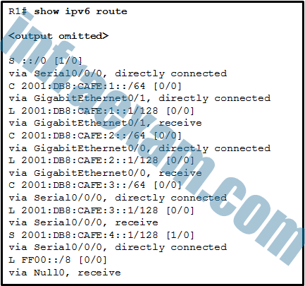
CCNA2 SRWE Practice Final Exam Answers v7 07 - forward the packet out GigabitEthernet0/0
- forward the packet out Serial0/0/0
- forward the packet out GigabitEthernet0/1
- drop the packet
Answers Explanation & Hints: The route ::/0 is the compressed form of the 0000:0000:0000:0000:0000:0000:0000:0000/0 default route. The default route is used if a more specific route is not found in the routing table.
-
What is a drawback of the local database method of securing device access that can be solved by using AAA with centralized servers?
- There is no ability to provide accountability.
- It is very susceptible to brute-force attacks because there is no username.
- The passwords can only be stored in plain text in the running configuration.
- User accounts must be configured locally on each device, which is an unscalable authentication solution.
Answers Explanation & Hints: The local database method of securing device access utilizes usernames and passwords that are configured locally on the router. This allows administrators to keep track of who logged in to the device and when. The passwords can also be encrypted in the configuration. However, the account information must be configured on each device where that account should have access, making this solution very difficult to scale.
-
Which three Wi-Fi standards operate in the 2.4GHz range of frequencies? (Choose three.)
- 802.11ac
- 802.11a
- 802.11n
- 802.11b
- 802.11g
-
Explanation & Hint: The Wi-Fi standards that operate in the 2.4GHz range of frequencies are:
- 802.11n – This standard can operate in both 2.4GHz and 5GHz frequencies.
- 802.11b – This was one of the first Wi-Fi standards, operating solely in the 2.4GHz frequency.
- 802.11g – This standard also operates in the 2.4GHz frequency and was designed to be faster than 802.11b while maintaining compatibility with it.
The 802.11ac standard operates exclusively in the 5GHz frequency range, and 802.11a also operates in the 5GHz frequency range, not in the 2.4GHz range.
-
Which command will create a static route on R2 in order to reach PC B?
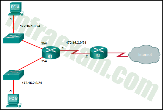
CCNA 2 v7 SRWE Final Exam Answers 34 - R2(config)# ip route 172.16.2.0 255.255.255.0 172.16.2.254
- R2(config)# ip route 172.16.2.0 255.255.255.0 172.16.3.1
- R2(config)# ip route 172.16.2.1 255.255.255.0 172.16.3.1
- R2(config)# ip route 172.16.3.0 255.255.255.0 172.16.2.254
Answers Explanation & Hints: The correct syntax is:
router(config)# ip route destination-network destination-mask {next-hop-ip-address | exit-interface}
If the local exit interface instead of the next-hop IP address is used then the route will be displayed as a directly connected route instead of a static route in the routing table. Because the network to be reached is 172.16.2.0 and the next-hop IP address is 172.16.3.1, the command is R2(config)# ip route 172.16.2.0 255.255.255.0 172.16.3.1
-
What is the effect of entering the switchport mode access configuration command on a switch?
- It disables DTP on a non-trunking interface.
- It disables an unused port.
- It manually enables a trunk link.
- It enables BPDU guard on a specific port.
-
Explanation & Hint: The effect of entering the
switchport mode accessconfiguration command on a switch is that it sets the specified interface to permanently operate as an access port, which is used to connect end devices such as computers and printers to the switch. This command does the following:- It disables DTP (Dynamic Trunking Protocol) on that interface. DTP is used on switch interfaces to negotiate if the port should become a trunk, but setting the port to access mode manually disables DTP because the port is no longer eligible to form a trunk, as it is explicitly designated for access mode.
Therefore, the correct statement is:
- It disables DTP on a non-trunking interface.
The command does not disable an unused port, manually enable a trunk link, or enable BPDU guard on a specific port. Those would be the effects of different commands.
-
Refer to the exhibit. Which statement shown in the output allows router R1 to respond to stateless DHCPv6 requests?
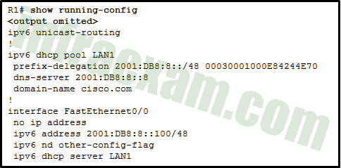
CCNA 2 v7 SRWE Final Exam Answers 35 - ipv6 nd other-config-flag
- ipv6 dhcp server LAN1
- prefix-delegation 2001:DB8:8::/48 00030001000E84244E70
- ipv6 unicast-routing
- dns-server 2001:DB8:8::8
Answers Explanation & Hints: The interface command ipv6 nd other-config-flag allows RA messages to be sent on this interface, indicating that additional information is available from a stateless DHCPv6 server.
-
Refer to the exhibit. The network administrator is configuring the port security feature on switch SWC. The administrator issued the command show port-security interface fa 0/2 to verify the configuration. What can be concluded from the output that is shown? (Choose three.)
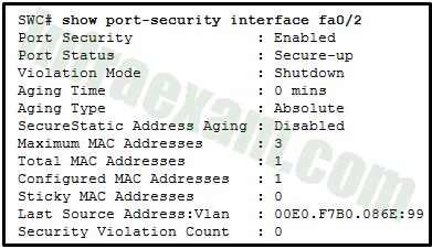
CCNA 2 v7 SRWE Final Exam Answers 36 - The port is configured as a trunk link.
- This port is currently up.
- The switch port mode for this interface is access mode.
- Three security violations have been detected on this interface.
- There is no device currently connected to this port.
- Security violations will cause this port to shut down immediately.
-
Explanation & Hint: Based on the output shown in the exhibit for the interface fa0/2 with port security enabled, the following conclusions can be made:
- This port is currently up: The “Port Status” is showing as “Secure-up,” which indicates that the interface is up and running and that port security is active.
- The switch port mode for this interface is access mode: Since port security is typically applied on access ports and the fact that the port is up with a single MAC address suggests that it is functioning as an access port.
- Security violations will cause this port to shut down immediately: The “Violation Mode” is set to “Shutdown.” This means that if a security violation occurs, the port will immediately go into the error-disabled state and stop forwarding frames.
The output does not indicate that the port is configured as a trunk link, nor does it suggest that three security violations have been detected on this interface (the “Security Violation Count” is 0). Additionally, it cannot be concluded that there is no device currently connected to this port; on the contrary, the presence of a “Last Source Address” suggests that a device is or recently was connected.
-
What are two reasons a network administrator would segment a network with a Layer 2 switch? (Choose two.)
- to isolate ARP request messages from the rest of the network
- to create more broadcast domains
- to enhance user bandwidth
- to eliminate virtual circuits
- to create fewer collision domains
- to isolate traffic between segments
Answers Explanation & Hints: A switch has the ability of creating temporary point-to-point connections between the directly-attached transmitting and receiving network devices. The two devices have full-bandwidth full-duplex connectivity during the transmission.
-
What action takes place when a frame entering a switch has a unicast destination MAC address appearing in the MAC address table?
- The switch resets the refresh timer on all MAC address table entries.
- The switch forwards the frame out of the specified port.
- The switch updates the refresh timer for the entry.
- The switch will forward the frame out all ports except the incoming port.
-
Explanation & Hint: When a frame entering a switch has a unicast destination MAC address that already appears in the MAC address table, the switch will update the refresh timer for the entry associated with that MAC address. This is because the MAC address table, also known as the CAM (Content Addressable Memory) table, maintains a time stamp for each dynamic entry.
Additionally, the switch forwards the frame out of the specific port associated with the destination MAC address. This action is part of the normal switch operation to direct frames only to the port where the destination device is located, thereby conserving bandwidth on other ports. It’s important to note that the switch does not reset the timer for all MAC address table entries, only for the entry corresponding to the destination MAC address of the frame.
-
A network administrator is using the router-on-a-stick model to configure a switch and a router for inter-VLAN routing. What configuration should be made on the switch port that connects to the router?
- Configure the port as a trunk port and assign it to VLAN1.
- Configure it as a trunk port and allow only untagged traffic.
- Configure the port as an 802.1q trunk port.
- Configure the port as an access port and a member of VLAN1.
Answers Explanation & Hints: The port on the switch that connects to the router interface should be configured as a trunk port. Once it becomes a trunk port, it does not belong to any particular VLAN and will forward traffic from various VLANs.
-
What is the effect of entering the switchport port-security configuration command on a switch?
- It enables port security globally on the switch.
- It dynamically learns the L2 address and copies it to the running configuration.
- It restricts the number of discovery messages, per second, to be received on the interface.
- It enables port security on an interface.
-
Explanation & Hint: Entering the
switchport port-securitycommand on a switch interface has the effect of enabling port security on that specific interface. Port security is a feature that allows you to restrict input to an interface by limiting and identifying MAC addresses of the workstations that are allowed to access the port. When you enable port security on an interface, the switch will start enforcing the restrictions that have been configured for that port such as limiting the number of MAC addresses or specifying exactly which MAC addresses can connect.
-
Users on a LAN are unable to get to a company web server but are able to get elsewhere. What should be done or checked?
- Ensure that the old default route has been removed from the company edge routers.
- Verify that the static route to the server is present in the routing table.
- Create a floating static route to that network.
- Check the configuration on the floating static route and adjust the AD.
-
Explanation & Hint:
-
Refer to the exhibit. A network administrator is configuring the router R1 for IPv6 address assignment. Based on the partial configuration, which IPv6 global unicast address assignment scheme does the administrator intend to implement?
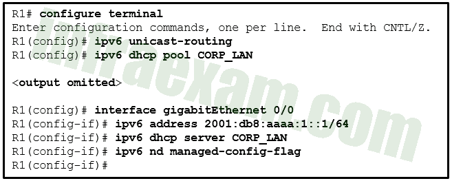
CCNA 2 v7 SRWE Final Exam Answers 37 - manual configuration
- stateful
- stateless
- SLAAC
-
Explanation & Hint: Based on the partial configuration provided in the exhibit, the IPv6 global unicast address assignment scheme the administrator intends to implement is “stateful”. This is indicated by the configuration lines that mention the setup of an IPv6 DHCP pool with the name CORP_LAN and the command
ipv6 dhcp server CORP_LANon the interface.This configuration specifies that the router is intended to act as a DHCPv6 server, providing IPv6 addresses and configuration parameters to clients. The
ipv6 nd managed-config-flagcommand indicates that the router should inform the clients that they should use DHCPv6 to obtain their address information as well as additional configuration parameters, which is a characteristic of stateful DHCPv6.
-
Match the step to each switch boot sequence description. (Not all options are used.)
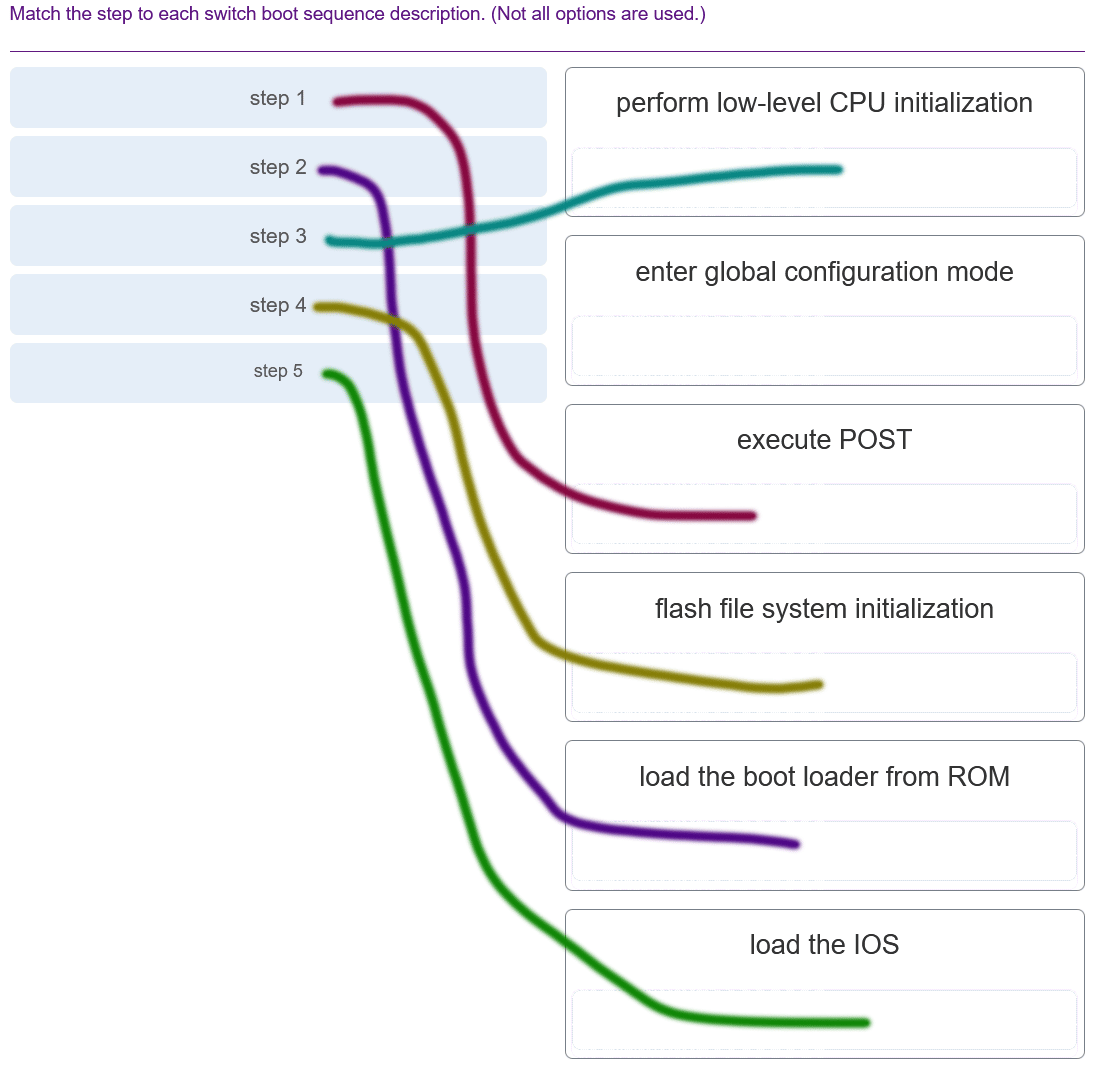
CCNA 2 v7 SRWE Final Exam Answers 006 Answers Explanation & Hints: The steps are:
1. execute POST
2. load the boot loader from ROM
3. CPU register initializations
4. flash file system initialization
5. load the IOS
6. transfer switch control to the IOS -
What protocol or technology disables redundant paths to eliminate Layer 2 loops?
- EtherChannel
- DTP
- STP
- VTP
-
Explanation & Hint: The protocol or technology that disables redundant paths to eliminate Layer 2 loops is STP, which stands for Spanning Tree Protocol. STP is essential in network environments to prevent loop conditions that can occur with redundant paths in a network, which can lead to major problems like broadcast storms and network failures. By selectively blocking certain paths, STP maintains a loop-free and efficient network topology.
-
During the AAA process, when will authorization be implemented?
- immediately after the determination of which resources a user can access
- immediately after an AAA client sends authentication information to a centralized server
- immediately after AAA accounting and auditing receives detailed reports
- immediately after successful authentication against an AAA data source
Answers Explanation & Hints: AAA authorization is implemented immediately after the user is authenticated against a specific AAA data source.
-
Which two protocols are used to provide server-based AAA authentication? (Choose two.)
- TACACS+
- RADIUS
- SNMP
- 802.1x
- SSH
-
Explanation & Hint: The two protocols used to provide server-based AAA (Authentication, Authorization, and Accounting) authentication are:
- TACACS+ (Terminal Access Controller Access-Control System Plus)
- RADIUS (Remote Authentication Dial-In User Service)
These protocols are specifically designed for managing network access control and are widely used for their robust security features. TACACS+ is commonly used in Cisco environments, while RADIUS is more broadly used across various network equipment and scenarios.