19.1.4 Lab – Implement a DMVPN Phase 3 Spoke-to-Spoke Topology Answers
| CCNP ENARSI v8 & 8.01 | |
| Final Exam Answers | |
| This Chapters 18 - 20 | |
| Chapters 18 - 20 Exam Answers | Online Test |
| Chapters 18 - 20 Quizzes Answers | Online Test |
| Next Chapters 21 - 23 | |
| Chapters 21 - 23 Exam Answers | Online Test |
| Chapters 21 - 23 Quizzes Answers | Online Test |
| CCNP ENARSI Packet Tracer Activity Files Answers | |
| 19.2.1 Packet Tracer – Configure GRE Answers | |
| 20.2.1 Packet Tracer – Configure and Verify a Site-to-Site IPsec VPN using CLI Answers | |
| CCNP ENARSI Student Lab Source Files Answers | |
| 18.1.2 Lab – Implement VRF-Lite Answers | |
| 19.1.2 Lab – Implement a GRE Tunnel Answers | |
| 19.1.3 Lab – Implement a DMVPN Phase 1 Hub-to-Spoke Topology Answers | |
| 19.1.4 Lab – Implement a DMVPN Phase 3 Spoke-to-Spoke Topology Answers | |
| 19.1.5 Lab – Implement an IPv6 DMVPN Phase 3 Spoke-to-Spoke Topology Answers | |
| 20.1.2 Lab – Configure Secure DMVPN Tunnels Answers | |
Lab – Implement a DMVPN Phase 3 Spoke-to-Spoke Topology (Answers Version)
Answers Note: Red font color or gray highlights indicate text that appears in the instructor copy only.
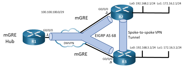
Topology

Addressing Table
|
Device |
Interface |
IPv4 Address |
|
R1 |
G0/0/1 |
192.0.2.1/30 |
|
R1 |
Tunnel 1 |
100.100.100.1/29 |
|
R2 |
G0/0/1 |
198.51.100.2/30 |
|
R2 |
Loopback 0 |
192.168.2.1/24 |
|
R2 |
Loopback 1 |
172.16.2.1/24 |
|
R2 |
Tunnel 1 |
100.100.100.2/29 |
|
R3 |
G0/0/1 |
203.0.113.2/30 |
|
R3 |
Loopback 0 |
192.168.3.1/24 |
|
R3 |
Loopback 1 |
172.16.3.1/24 |
|
R3 |
Tunnel 1 |
100.100.100.3/29 |
Objectives
In this lab, you will create a Dynamic Multipoint Virtual Private Network (DMVPN) that consists of a hub router with two spokes. You will implement a DMVPN Phase 3 spoke-to-spoke topology.
Part 1: Build the Network and Configure Basic Device Settings
Part 2: Configure DMVPN Phase 3
Part 3: Verify DMVPN Phase 3
Background / Scenario
In this lab, you will modify a DMVPN Phase 1 network to create Phase 3 spoke-to-spoke network. The configuration from the previous Phase 1 lab are required as the starting point for this lab.
Phase 3 improved upon Phase 2 by using a different mechanism for routing between destinations in spoke-to-spoke tunnels. Because of this, Phase 3 can be seen as superseding Phase 2. For that reason, there is no Phase 2 lab.
In DMVPN Phase 3, the spoke routers create routing table entries in which NHRP manipulates the routing information for tunnel destinations by overriding the next hop that was determined by the routing protocol. NHRP provides the actual destination network as the next hop. This enables the distribution of route summaries from the hub router to the spokes. Finally, Phase 3 enables a hierarchical tree-based VPN architecture in which central hub routers connect other, regional hubs and their spokes. This allows for the establishment of tunnels between routers that are not connected to the same regional hub.
In Phase 1 DMVPN, all spoke router traffic must pass through the hub router, as shown in the topology diagram.

In a Phase 3 spoke-spoke DMVPN, traffic initially travels to the hub. The traffic then travels directly between the spoke routers over the spoke-to-spoke tunnel.
Note: This lab does not include the configuration of IPSec to secure the tunnels. This essential procedure will be covered in a later lab.
Note: This lab is an exercise in configuring and verifying various implementations of DMVPN topologies and does not reflect networking best practices.
Note: The routers used with CCNP hands-on labs are the Cisco 4221 with Cisco IOS XE Release 16.9.4 (universalk9 image). The Layer 3 switch is a Cisco Catalyst 3650 with Cisco IOS XE Release 16.9.4 (universalk9 image). Other routers, Layer 3 switches, and Cisco IOS versions can be used. Depending on the model and Cisco IOS version, the commands available and the output produced might vary from what is shown in the labs.
Note: Make sure that the devices have been erased and have no startup configurations. If you are unsure, please contact your instructor.
Answers Note: Refer to the Answers Lab Manual for the procedures to initialize and reload devices.
Required Resources
- 3 Routers (Cisco 4221 with Cisco IOS XE Release 16.9.4 universal image or comparable)
- 1 Layer 3 switch (Cisco 3650 with Cisco IOS Release 16.9.4 universal image or comparable)
- 1 PC (Choice of operating system with a terminal emulation program installed)
- Console cables to configure the Cisco IOS devices via the console ports
- Ethernet cables as shown in the topology
Initial Configurations
Students will use the devices that were configured for the “Lab – Implement a DMVPN Phase 1 Hub-to-Spoke Topology”. If they do not have the preconfigured devices, they could benefit by practicing configuration of DMVPN Phase 1 from that lab. Otherwise, they could paste the initial configurations into the devices. Initial configurations are provided here.
R1 hub router
hostname R1
no ip domain lookup
banner motd # R1, Implement DMVPN Hub #
line con 0
exec-timeout 0 0
logging synchronous
exit
line vty 0 4
privilege level 15
password cisco123
exec-timeout 0 0
logging synchronous
login
exit
interface g0/0/1
ip address 192.0.2.1 255.255.255.252
no shutdown
exit
interface tunnel 1
tunnel mode gre multipoint
tunnel source g0/0/1
tunnel key 999
ip address 100.100.100.1 255.255.255.248
ip nhrp network-id 1
ip nhrp authentication NHRPauth
ip nhrp map multicast dynamic
bandwidth 4000
ip mtu 1400
ip tcp adjust-mss 1360
exit
router eigrp DMVPN_TUNNEL_NET
address-family ipv4 unicast autonomous-system 68
eigrp router-id 1.1.1.1
network 100.100.100.0 255.255.255.248
af-interface tunnel 1
no split-horizon
router eigrp DMVPN_TRANS_NET
address-family ipv4 unicast autonomous-system 168
eigrp router-id 10.1.1.1
network 192.0.2.0 255.255.255.252
end
R2 spoke router 1
hostname R2
no ip domain lookup
banner motd # R2, Implement DMVPN Spoke 1 #
line con 0
exec-timeout 0 0
logging synchronous
exit
line vty 0 4
privilege level 15
password cisco123
exec-timeout 0 0
logging synchronous
login
exit
interface g0/0/1
ip address 198.51.100.2 255.255.255.252
no shutdown
exit
interface loopback 0
ip address 192.168.2.1 255.255.255.0
no shutdown
exit
interface loopback 1
ip address 172.16.2.1 255.255.255.0
no shutdown
exit
interface tunnel 1
tunnel mode gre ip
tunnel source loopback 0
tunnel destination 192.0.2.1
tunnel key 999
ip address 100.100.100.2 255.255.255.248
ip nhrp network-id 1
ip nhrp authentication NHRPauth
ip nhrp nhs 100.100.100.1
ip nhrp map multicast 192.0.2.1
ip nhrp map 100.100.100.1 192.0.2.1
ip mtu 1400
ip tcp adjust-mss 1360
router eigrp DMVPN_TUNNEL_NET
address-family ipv4 unicast autonomous-system 68
eigrp router-id 2.2.2.2
network 100.100.100.0 255.255.255.248
network 172.16.2.0 255.255.255.0
eigrp stub connected
router eigrp DMVPN_TRANS_NET
address-family ipv4 unicast autonomous-system 168
eigrp router-id 20.2.2.2
network 198.51.100.0 255.255.255.252
network 192.168.2.0 255.255.255.0
end
Router R3 spoke 2
hostname R3
no ip domain lookup
banner motd # R3, Implement DMVPN Spoke 2 #
line con 0
exec-timeout 0 0
logging synchronous
exit
line vty 0 4
privilege level 15
password cisco123
exec-timeout 0 0
logging synchronous
login
exit
interface g0/0/1
ip address 203.0.113.2 255.255.255.252
no shutdown
exit
interface loopback 0
ip address 192.168.3.1 255.255.255.0
no shutdown
exit
interface loopback 1
ip address 172.16.3.1 255.255.255.0
no shutdown
exit
interface tunnel 1
tunnel mode gre ip
tunnel source loopback 0
tunnel destination 192.0.2.1
tunnel key 999
ip address 100.100.100.3 255.255.255.248
ip nhrp network-id 1
ip nhrp authentication NHRPauth
ip nhrp nhs 100.100.100.1
ip nhrp map multicast 192.0.2.1
ip nhrp map 100.100.100.1 192.0.2.1
ip mtu 1400
ip tcp adjust-mss 1360
router eigrp DMVPN_TUNNEL_NET
address-family ipv4 unicast autonomous-system 68
eigrp router-id 3.3.3.3
network 100.100.100.0 255.255.255.248
network 172.16.3.0 255.255.255.0
eigrp stub connected
router eigrp DMVPN_TRANS_NET
address-family ipv4 unicast autonomous-system 168
eigrp router-id 30.3.3.3
network 203.0.113.0 255.255.255.252
network 192.168.3.0 255.255.255.0
eigrp stub connected
end
Layer 3 Switch DMVPN
hostname DMVPN
no ip domain lookup
ip routing
banner motd # DMVPN, DMVPN cloud switch #
line con 0
exec-timeout 0 0
logging synchronous
exit
line vty 0 4
privilege level 15
password cisco123
exec-timeout 0 0
logging synchronous
login
interface g1/0/11
no switchport
ip address 192.0.2.2 255.255.255.252
no shutdown
exit
interface g1/0/12
no switchport
ip address 198.51.100.1 255.255.255.252
no shutdown
exit
interface g1/0/13
no switchport
ip address 203.0.113.1 255.255.255.252
no shutdown
exit
router eigrp DMVPN_TRANS_NET
address-family ipv4 unicast autonomous-system 168
eigrp router-id 40.4.4.4
network 192.0.2.0 255.255.255.252
network 198.51.100.0 255.255.255.252
network 203.0.113.0 255.255.255.252
end
Instructions
Part 1:Build the Network and Configure Basic Device Settings
In Part 1, you will set up the network topology and configure basic settings if the network is not already configured. This lab uses the same topology and final configurations from the Lab – Implement a DMVPN Phase 1 Hub-to-Spoke Topology.
Step 1:Cable the network as shown in the topology.
Attach the devices as shown in the topology diagram, and cable as necessary.
Step 2:Configure initial settings for each router and the Layer 3 switch.
Console into each device, enter global configuration mode, and apply the initial settings for the lab if the devices are not already configured.
Step 3:Verify connectivity in the network.
- From R1, ping the loopback interfaces of R2 and R3. All pings should be successful. This verifies that full connectivity exists in the underlay, or transport, network.
Open configuration window
R1# ping 192.168.2.1
Type escape sequence to abort.
Sending 5, 100-byte ICMP Echos to 192.168.3.1, timeout is 2 seconds:
!!!!!
Success rate is 100 percent (5/5), round-trip min/avg/max = 1/1/1 ms
R1# ping 192.168.3.1
Type escape sequence to abort.
Sending 5, 100-byte ICMP Echos to 192.168.3.1, timeout is 2 seconds:
!!!!!
Success rate is 100 percent (5/5), round-trip min/avg/max = 1/1/1 ms
Close configuration window
- From R2 traceroute to the Loopback 1 interface of R3. You should see the following output. Note that traffic from the R2 spoke router travels through the R1 hub router to reach R3. This is the DMVPN Phase 1 traffic flow. Repeat the traceroute to verify this result.
Open configuration window
R2# traceroute 172.16.3.1
Type escape sequence to abort.
Tracing the route to 172.16.3.1
VRF info: (vrf in name/id, vrf out name/id)
1 100.100.100.1 1 msec 1 msec 1 msec
2 100.100.100.3 1 msec *2 msec
- On the spoke routers, issue the show ip route command. Note that EIGRP shows the next hop for the Loopback 1 networks to be the R1 tunnel interface address. That is, both spoke routers will use R1 to send traffic on the overlay network to the LANs.
R2# show ip route eigrp | begin Gateway
Gateway of last resort is not set
172.16.0.0/16 is variably subnetted, 3 subnets, 2 masks
D172.16.3.0/24 [90/102400640] via 100.100.100.1, 00:21:14, Tunnel1
192.0.2.0/30 is subnetted, 1 subnets
D192.0.2.0 [90/15360] via 198.51.100.1, 00:21:21, GigabitEthernet0/0/1
D192.168.3.0/24
[90/16000] via 198.51.100.1, 00:21:21, GigabitEthernet0/0/1
203.0.113.0/30 is subnetted, 1 subnets
D203.0.113.0
[90/15360] via 198.51.100.1, 00:21:21, GigabitEthernet0/0/1
Close configuration window
open configuration window
R3# show ip route eigrp | begin Gateway
Gateway of last resort is not set
172.16.0.0/16 is variably subnetted, 3 subnets, 2 masks
D172.16.2.0/24 [90/102400640] via 100.100.100.1, 00:22:49, Tunnel1
192.0.2.0/30 is subnetted, 1 subnets
D192.0.2.0 [90/15360] via 203.0.113.1, 00:22:59, GigabitEthernet0/0/1
D192.168.2.0/24
[90/16000] via 203.0.113.1, 00:22:59, GigabitEthernet0/0/1
198.51.100.0/30 is subnetted, 1 subnets
D198.51.100.0
[90/15360] via 203.0.113.1, 00:22:59, GigabitEthernet0/0/1
Close configuration window
Part 2:Configure DMVPN Phase 3
In this part of the lab, you will configure DMVPN Phase 3 to create DMVPN tunnels between the spoke routers. Initially, the services of the hub are required to begin data transfer over the VPN. However, the hub multipoint tunnel interface detects that traffic is “hairpinning,” or exiting the interface on which it was received. The hub router sends redirect messages to the two spoke routers that are communicating. The spoke routers use the redirect messages to dynamically create a tunnel to connect to each other. In this way, the hub router does not need to forward spoke-to-spoke traffic after the setup of the spoke-to-spoke tunnel.
Step 1:Modify the tunnel interfaces on the spoke routers.
This lab builds on the Phase 1 lab that was previously completed. On the spoke routers R2 and R3, modify the configurations of the Tunnel 1 interfaces. The network will essentially be configured for DMVPN Phase 2 at the conclusion of this step.
- On R2, set the tunnel mode to mGRE. You will see an error message that states that point-to-multipoint tunnels can not have static tunnel destinations configured.
Open configuration window
R2(config)# interface tunnel 1
R2(config-if)# tunnel mode gre multipoint
Tunnel set mode failed. p2mp tunnels cannot have a tunnel destination.
- Remove the tunnel destination configuration. You will see the interface go down and the EIGRP adjacency with the hub router be lost. Reconfigure the tunnel mode as GRE multipoint. You will see the interface come back up and the EIGRP adjacency will be restored.
R2(config-if)# no tunnel destination
*Mar 27 12:46:31.496: %LINEPROTO-5-UPDOWN: Line protocol on Interface Tunnel1, changed state to down
*Mar 27 12:46:31.499: %DUAL-5-NBRCHANGE: EIGRP-IPv4 68: Neighbor 100.100.100.1 (Tunnel1) is down: interface down
R2(config-if)# tunnel mode gre multipoint
*Mar 27 12:46:46.629: %LINEPROTO-5-UPDOWN: Line protocol on Interface Tunnel1, changed state to up
*Mar 27 12:46:48.008: %DUAL-5-NBRCHANGE: EIGRP-IPv4 68: Neighbor 100.100.100.1 (Tunnel1) is up: new adjacency
Close configuration window
- Repeat this process for the R3 tunnel interface. At this point, you have essentially configured DMVPN Phase 2. You may want to verify the R1 can ping R2 and R3 loopbacks again.
- Verify the tunnel interface configuration is now using mGRE with the show interface tunnel 1 command.
Open configuration window
R3# show interface tunnel 1 | include Tunnel protocol
Tunnel protocol/transport multi-GRE/IP
Close configuration window
Step 2:Modify the configuration on the spoke routers to enable NHRP routing shortcuts.
Configure the spoke router interfaces on R2 and R3 to enable NHRP to add spoke networks as next hops in the EIGRP routing table. The hub router will send NHRP redirect messages to the spokes. NHRP uses information in the redirect messages to manipulate the EIGRP routing table and create the next hop shortcuts.
Open configuration window
R2(config)# interface tunnel 1
R2(config-if)# ip nhrp shortcut
Close configuration window
Open configuration window
R3(config)# interface tunnel 1
R3(config-if)# ip nhrp shortcut
Close configuration window
Step 3:Modify the configuration of hub router to send NHRP redirect messages.
The Tunnel 1 interface of the hub router needs to be configured to send NHRP redirect messages to the spokes when it detects spoke-to-spoke traffic. Issue the ip nhrp redirect command on R1.
Open configuration window
R1(config)# interface tunnel 1
R1(config-if)# ip nhrp redirect
Close configuration window
Part 3:Verify DMVPN Phase 3
Now that DMVPN Phase 3 is complete, you can test dynamic spoke-to-spoke tunnel creation.
Step 1:Observe dynamic tunnel creation.
- Return to R2. Initiate a traceroute to the simulated LAN interface on R3. The path will pass through R1 as it does in DMVPN Phase 1.
Open configuration window
R2# traceroute 172.16.3.1
Type escape sequence to abort.
Tracing the route to 172.16.3.1
VRF info: (vrf in name/id, vrf out name/id)
1 100.100.100.1 1 msec 1 msec 1 msec
2 100.100.100.3 1 msec *2 msec
- Issue the traceroute command again. You will now see that R1 has enabled direct spoke-to-spoke communication between R2 and R3. This tunnel will expire after ten minutes by default. The tunnel dynamically reopens after data is sent to the spoke router again.
R2# traceroute 172.16.3.1
Type escape sequence to abort.
Tracing the route to 172.16.3.1
VRF info: (vrf in name/id, vrf out name/id)
1 100.100.100.3 1 msec *1 msec
Close configuration window
- Repeat the traceroute commands on R3 to 172.16.2.1.
Step 2:View the routing table.
- On R2, issue the command to view the EIGRP routes that are in the routing table. Compare this routing table with the DMVPN Phase 1 routing from earlier in this lab. You should see that EIGRP shows the next hop interface to the 172.16.3.0 network to be the unchanged. However, the route is flagged with % indicating that NHRP is has overridden the next hop entry with its own value. Also notice that an NHRP route now appears in the routing table. This route indicates that the tunnel interface for R3 is considered to be directly connected by NHRP.
Open configuration window
R2# show ip route
Codes: L – local, C – connected, S – static, R – RIP, M – mobile, B – BGP
D – EIGRP, EX – EIGRP external, O – OSPF, IA – OSPF inter area
N1 – OSPF NSSA external type 1, N2 – OSPF NSSA external type 2
E1 – OSPF external type 1, E2 – OSPF external type 2
i – IS-IS, su – IS-IS summary, L1 – IS-IS level-1, L2 – IS-IS level-2
ia – IS-IS inter area, * – candidate default, U – per-user static route
o – ODR, P – periodic downloaded static route, H – NHRP, l – LISP
a – application route
+ – replicated route, % – next hop override, p – overrides from PfR
Gateway of last resort is not set
100.0.0.0/8 is variably subnetted, 3 subnets, 2 masks
C100.100.100.0/29 is directly connected, Tunnel1
L100.100.100.2/32 is directly connected, Tunnel1
H100.100.100.3/32 is directly connected, 00:03:53, Tunnel1
172.16.0.0/16 is variably subnetted, 3 subnets, 2 masks
C172.16.2.0/24 is directly connected, Loopback1
L172.16.2.1/32 is directly connected, Loopback1
D%172.16.3.0/24 [90/102400640] via 100.100.100.1, 02:53:00, Tunnel1
192.0.2.0/30 is subnetted, 1 subnets
D192.0.2.0 [90/15360] via 198.51.100.1, 03:38:15, GigabitEthernet0/0/1
192.168.2.0/24 is variably subnetted, 2 subnets, 2 masks
C192.168.2.0/24 is directly connected, Loopback0
L192.168.2.1/32 is directly connected, Loopback0
D192.168.3.0/24
[90/16000] via 198.51.100.1, 03:38:15, GigabitEthernet0/0/1
198.51.100.0/24 is variably subnetted, 2 subnets, 2 masks
C198.51.100.0/30 is directly connected, GigabitEthernet0/0/1
L198.51.100.2/32 is directly connected, GigabitEthernet0/0/1
203.0.113.0/30 is subnetted, 1 subnets
D203.0.113.0
[90/15360] via 198.51.100.1, 03:38:15, GigabitEthernet0/0/1
- View the value that is actually used for the next hop address. It is marked with NHO for next hop override. This indicates that the next hop to 172.16.3.0 is R3 through the spoke-to-spoke tunnel.
R2# show ip route next-hop-override | begin Gateway
Gateway of last resort is not set
100.0.0.0/8 is variably subnetted, 3 subnets, 2 masks
C100.100.100.0/29 is directly connected, Tunnel1
L100.100.100.2/32 is directly connected, Tunnel1
H100.100.100.3/32 is directly connected, 00:17:39, Tunnel1
172.16.0.0/16 is variably subnetted, 3 subnets, 2 masks
C172.16.2.0/24 is directly connected, Loopback1
L172.16.2.1/32 is directly connected, Loopback1
D%172.16.3.0/24 [90/102400640] via 100.100.100.1, 00:17:41, Tunnel1
[NHO][90/255] via 100.100.100.3, 00:17:39, Tunnel1
192.0.2.0/30 is subnetted, 1 subnets
D192.0.2.0 [90/15360] via 198.51.100.1, 01:02:56, GigabitEthernet0/0/1
192.168.2.0/24 is variably subnetted, 2 subnets, 2 masks
C192.168.2.0/24 is directly connected, Loopback0
L192.168.2.1/32 is directly connected, Loopback0
D192.168.3.0/24
[90/16000] via 198.51.100.1, 01:02:56, GigabitEthernet0/0/1
198.51.100.0/24 is variably subnetted, 2 subnets, 2 masks
C198.51.100.0/30 is directly connected, GigabitEthernet0/0/1
L198.51.100.2/32 is directly connected, GigabitEthernet0/0/1
203.0.113.0/30 is subnetted, 1 subnets
D203.0.113.0
[90/15360] via 198.51.100.1, 01:02:56, GigabitEthernet0/0/1
Step 3:Verify the DMVPN
- View the DMVPN information with the spoke-to-spoke tunnel open. The first entry in the table is the static tunnel between R2 and the hub router. The DLX flag indicates that the entry is the local network. The DT1 entry is the route through the overlay network, and the DT2 entry the next hop override to the target network. If the spoke-to-spoke tunnel has closed, generate traffic to reopen it with traceroute.
R2# show dmvpn detail
Legend: Attrb –> S – Static, D – Dynamic, I – Incomplete
N – NATed, L – Local, X – No Socket
T1 – Route Installed, T2 – Nexthop-override
C – CTS Capable, I2 – Temporary
# Ent –> Number of NHRP entries with same NBMA peer
NHS Status: E –> Expecting Replies, R –> Responding, W –> Waiting
UpDn Time –> Up or Down Time for a Tunnel
==========================================================================
Interface Tunnel1 is up/up, Addr. is 100.100.100.2, VRF “”
Tunnel Src./Dest. addr: 192.168.2.1/Multipoint, Tunnel VRF “”
Protocol/Transport: “multi-GRE/IP”, Protect “”
Interface State Control: Disabled
nhrp event-publisher : Disabled
IPv4 NHS:
100.100.100.1RE priority = 0 cluster = 0
Type:Spoke, Total NBMA Peers (v4/v6): 3
# EntPeer NBMA Addr Peer Tunnel Add StateUpDn Tm AttrbTarget Network
—– ————— ————— —– ——– —– —————–
1 192.0.2.1100.100.100.1UP 03:22:47S100.100.100.1/32
1 192.168.2.1100.100.100.2UP 00:01:36DLX100.100.100.2/32
2 192.168.3.1100.100.100.3UP 00:01:36DT1100.100.100.3/32
192.168.3.1100.100.100.3UP 00:01:36DT2172.16.3.0/24
Crypto Session Details:
——————————————————————————–
Pending DMVPN Sessions:
Close configuration window
- Repeat this command on R3.
Step 4:View NHRP Mappings
Note: If it has been more than 10 minutes since you completed your traceroutes, repeat them now to re-establish the spoke-to-spoke tunnels.
- On R2 and R3, issue the show ip nhrp detail command to view the NHRP information for the routers. Note the correspondence between the entries in the output of this command with the output from the show dmvpn detail command. The first entry is the static entry to the hub router. The second entry is the local route, corresponding to the DTX entry in output above. The third entry corresponds to the DT1 entry and is flagged with router nhop rib. This indicates that the router has an explicit method to reach the tunnel IP address using an NBMA address and has an associated route installed in the routing table.
The flag rib nho indicates that the router has found an identical route in the routing table that belongs to a different protocol (EIGRP in this case.). NHRP has overridden the other protocol’s next-hop entry for the network by installing a next-hop shortcut in the routing table. This corresponds to the DT2 entry in the show dmvpn detail output.
Open configuration window
R2# show ip nhrp detail
100.100.100.1/32 via 100.100.100.1
Tunnel1 created 04:03:01, never expire
Type: static, Flags:
NBMA address: 192.0.2.1
Preference: 255
100.100.100.2/32 via 100.100.100.2
Tunnel1 created 00:00:21, expire 00:09:38
Type: dynamic, Flags: router unique local
NBMA address: 192.168.2.1
Preference: 255
(no-socket)
Requester: 100.100.100.3 Request ID: 9
100.100.100.3/32 via 100.100.100.3
Tunnel1 created 00:00:21, expire 00:09:38
Type: dynamic, Flags: router nhop rib
NBMA address: 192.168.3.1
Preference: 255
172.16.3.0/24 via 100.100.100.3
Tunnel1 created 00:00:21, expire 00:09:38
Type: dynamic, Flags: router rib nho
NBMA address: 192.168.3.1
Preference: 255
Close configuration window
- You have successfully configured a DMVPN Phase 3 network.
Router Interface Summary Table
|
Router Model |
Ethernet Interface #1 |
Ethernet Interface #2 |
Serial Interface #1 |
Serial Interface #2 |
|
1800 |
Fast Ethernet 0/0 (F0/0) |
Fast Ethernet 0/1 (F0/1) |
Serial 0/0/0 (S0/0/0) |
Serial 0/0/1 (S0/0/1) |
|
1900 |
Gigabit Ethernet 0/0 (G0/0) |
Gigabit Ethernet 0/1 (G0/1) |
Serial 0/0/0 (S0/0/0) |
Serial 0/0/1 (S0/0/1) |
|
2801 |
Fast Ethernet 0/0 (F0/0) |
Fast Ethernet 0/1 (F0/1) |
Serial 0/1/0 (S0/1/0) |
Serial 0/1/1 (S0/1/1) |
|
2811 |
Fast Ethernet 0/0 (F0/0) |
Fast Ethernet 0/1 (F0/1) |
Serial 0/0/0 (S0/0/0) |
Serial 0/0/1 (S0/0/1) |
|
2900 |
Gigabit Ethernet 0/0 (G0/0) |
Gigabit Ethernet 0/1 (G0/1) |
Serial 0/0/0 (S0/0/0) |
Serial 0/0/1 (S0/0/1) |
|
4221 |
Gigabit Ethernet 0/0/0 (G0/0/0) |
Gigabit Ethernet 0/0/1 (G0/0/1) |
Serial 0/1/0 (S0/1/0) |
Serial 0/1/1 (S0/1/1) |
|
4300 |
Gigabit Ethernet 0/0/0 (G0/0/0) |
Gigabit Ethernet 0/0/1 (G0/0/1) |
Serial 0/1/0 (S0/1/0) |
Serial 0/1/1 (S0/1/1) |
Note: To find out how the router is configured, look at the interfaces to identify the type of router and how many interfaces the router has. There is no way to effectively list all the combinations of configurations for each router class. This table includes identifiers for the possible combinations of Ethernet and Serial interfaces in the device. The table does not include any other type of interface, even though a specific router may contain one. An example of this might be an ISDN BRI interface. The string in parenthesis is the legal abbreviation that can be used in Cisco IOS commands to represent the interface.
End of document
Device Configs – Final
Router R1
enable
configure terminal
hostname R1
no ip domain lookup
banner motd # R1, Implement DMVPN Hub #
line con 0
exec-timeout 0 0
logging synchronous
exit
line vty 0 4
privilege level 15
password cisco123
exec-timeout 0 0
logging synchronous
login
exit
interface g0/0/1
ip address 192.0.2.1 255.255.255.252
no shutdown
exit
interface tunnel 1
tunnel mode gre multipoint
tunnel source g0/0/1
tunnel key 999
ip address 100.100.100.1 255.255.255.248
ip nhrp network-id 1
ip nhrp authentication NHRPauth
ip nhrp map multicast dynamic
ip nhrp redirect
bandwidth 4000
ip mtu 1400
ip tcp adjust-mss 1360
exit
router eigrp DMVPN_TUNNEL_NET
address-family ipv4 unicast autonomous-system 68
eigrp router-id 1.1.1.1
network 100.100.100.0 255.255.255.248
af-interface tunnel 1
no split-horizon
router eigrp DMVPN_TRANS_NET
address-family ipv4 unicast autonomous-system 168
eigrp router-id 10.1.1.1
network 192.0.2.0 255.255.255.252
end
Router R2
enable
configure terminal
hostname R2
no ip domain lookup
banner motd # R2, Implement DMVPN Spoke 1 #
line con 0
exec-timeout 0 0
logging synchronous
exit
line vty 0 4
privilege level 15
password cisco123
exec-timeout 0 0
logging synchronous
login
exit
interface g0/0/1
ip address 198.51.100.2 255.255.255.252
no shutdown
exit
interface loopback 0
ip address 192.168.2.1 255.255.255.0
no shutdown
exit
interface loopback 1
ip address 172.16.2.1 255.255.255.0
no shutdown
exit
interface tunnel 1
tunnel mode gre multipoint
tunnel source loopback 0
no tunnel destination
tunnel key 999
ip address 100.100.100.2 255.255.255.248
ip nhrp network-id 1
ip nhrp authentication NHRPauth
ip nhrp nhs 100.100.100.1
ip nhrp map multicast 192.0.2.1
ip nhrp map 100.100.100.1 192.0.2.1
ip nhrp shortcut
ip mtu 1400
ip tcp adjust-mss 1360
router eigrp DMVPN_TUNNEL_NET
address-family ipv4 unicast autonomous-system 68
eigrp router-id 2.2.2.2
network 100.100.100.0 255.255.255.248
network 172.16.2.0 255.255.255.0
eigrp stub connected
router eigrp DMVPN_TRANS_NET
address-family ipv4 unicast autonomous-system 168
eigrp router-id 20.2.2.2
network 198.51.100.0 255.255.255.252
network 192.168.2.0 255.255.255.0
end
Router R3
enable
configure terminal
hostname R3
no ip domain lookup
banner motd # R3, Implement DMVPN Spoke 2 #
line con 0
exec-timeout 0 0
logging synchronous
exit
line vty 0 4
privilege level 15
password cisco123
exec-timeout 0 0
logging synchronous
login
exit
interface g0/0/1
ip address 203.0.113.2 255.255.255.252
no shutdown
exit
interface loopback 0
ip address 192.168.3.1 255.255.255.0
no shutdown
exit
interface loopback 1
ip address 172.16.3.1 255.255.255.0
no shutdown
exit
interface tunnel 1
tunnel mode gre multipoint
tunnel source loopback 0
no tunnel destination
tunnel key 999
ip address 100.100.100.3 255.255.255.248
ip nhrp network-id 1
ip nhrp authentication NHRPauth
ip nhrp nhs 100.100.100.1
ip nhrp map multicast 192.0.2.1
ip nhrp map 100.100.100.1 192.0.2.1
ip nhrp shortcut
ip mtu 1400
ip tcp adjust-mss 1360
router eigrp DMVPN_TUNNEL_NET
address-family ipv4 unicast autonomous-system 68
eigrp router-id 3.3.3.3
network 100.100.100.0 255.255.255.248
network 172.16.3.0 255.255.255.0
eigrp stub connected
router eigrp DMVPN_TRANS_NET
address-family ipv4 unicast autonomous-system 168
eigrp router-id 30.3.3.3
network 203.0.113.0 255.255.255.252
network 192.168.3.0 255.255.255.0
eigrp stub connected
end
| CCNP ENARSI v8 & 8.01 | |
| Final Exam Answers | |
| This Chapters 18 - 20 | |
| Chapters 18 - 20 Exam Answers | Online Test |
| Chapters 18 - 20 Quizzes Answers | Online Test |
| Next Chapters 21 - 23 | |
| Chapters 21 - 23 Exam Answers | Online Test |
| Chapters 21 - 23 Quizzes Answers | Online Test |
| CCNP ENARSI Packet Tracer Activity Files Answers | |
| 19.2.1 Packet Tracer – Configure GRE Answers | |
| 20.2.1 Packet Tracer – Configure and Verify a Site-to-Site IPsec VPN using CLI Answers | |
| CCNP ENARSI Student Lab Source Files Answers | |
| 18.1.2 Lab – Implement VRF-Lite Answers | |
| 19.1.2 Lab – Implement a GRE Tunnel Answers | |
| 19.1.3 Lab – Implement a DMVPN Phase 1 Hub-to-Spoke Topology Answers | |
| 19.1.4 Lab – Implement a DMVPN Phase 3 Spoke-to-Spoke Topology Answers | |
| 19.1.5 Lab – Implement an IPv6 DMVPN Phase 3 Spoke-to-Spoke Topology Answers | |
| 20.1.2 Lab – Configure Secure DMVPN Tunnels Answers | |