2.7.3 Packet Tracer – Multiarea OSPF Exploration – Physical Mode (Part 3) Answers
Packet Tracer – OSPF Multiarea Exploration – Physical Mode (Part 3) (Answers Version)
Answers Note: Red font color or gray highlights indicate text that appears in the Answers copy only.
Objectives
Part 1: Evaluate Network Operation of Single Area OSPF
Part 2: Evaluate Network Operation of Multiarea OSPF
Part 3: Configure a New Area and Attach to Area 0 Through the Internet
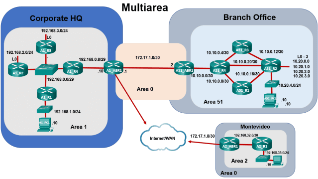
Topology

Background / Scenario
Part 1: The Beginning
Casual Recording Company, based in Sao Paulo, Brazil, provides self-serve, mini-recording studios around the city so that anyone can rent a timeslot and record their songs by themselves. CRC began with a single– area OSPF network located in one building. This idea was very popular and consequently the business has grown, causing the company to expand into a branch office in a second building at the far end of the city. They continued to use single-area OSPF. You will evaluate the impact of the expanded network.
Part 2: Business is Booming
The IT department in CRC decided to migrate to a multiarea OSPF network. You will evaluate the impact and benefits derived from the change to determine if it was a good decision or not.
Part 3: CRC Expansion Continues
CRC has continued to grow and will open a new branch office in Montevideo, Uruguay. You will configure the Area Border Router for the new area and physically connect the branch office network to the corporate headquarters network through the internet.
Instructions
Part 3: Configure a New Area and Attach to Area 0 Through the Internet
In this part, CRC is still expanding and has decided to open another office in a Montevideo, Uruguay. The internet link between Sao Paulo and Montevideo is a submarine cable. For more information, search the internet for pictures of “fiber links between Sao Paulo and Montevideo”.
Step 1: Complete the physical cabling to connect Area 0 to Area 2.
- You should now see an icon for Montevideo. If not, adjust the scroll bars so you can see both cities and the Internet/WAN.
- Click Connections in the Bottom Toolbar, and then click Fiber cable. Click Sao Paulo and select Corporate Headquarters > HQ Wiring Closet > Rack > A1_ABR1 > GigabitEthernet2/0. Next, click Internet/WAN > Internet/WAN Wiring Closet > Rack > WAN_R1 > GigabitEthernet1/0.
- Select another fiber cable from the toolbar and, using the same procedure as above, click Internet/WAN > Internet/WAN Wiring Closet > Rack > WAN_R2 > GigabitEthernet1/0. Next, click Montevideo > Montevideo Branch Office > Montevideo Branch Office Wiring Closet > Rack > A2_ABR1 > GigabitEthernet0/0.
Step 2: Configure OSPF on router A2_ABR1.
A2_ABR1 is already configured, with the exception of OSPF. In this step, you will configure the router to be an area border router connecting Area 2 to the rest of the network.
- Click Montevideo to enter city view. Notice there is a Branch Office building with the fiber link you just created.
- Click Branch Office, and then the rack icon that represents the Branch Office Wiring Closet.
- Click A2_ABR1, and then select the CLI tab.
- Enable OSPF on router A2_ABR1 and set the router ID to 172.17.1.10
A2_ABR1(config)# router ospf 1
A2_ABR1(config-router)# router-id 172.17.1.10
- Configure the 192.168.32.0/32 network to be in Area 2 and the 172.17.1.8/32 network to be in Area 0
A2_ABR1(config-router)# network 192.168.32.0 0.0.0.3 area 2
A2_ABR1(config-router)# network 172.17.1.8 0.0.0.3 area 0
- Configure summarization on router A2_ABR1 so that it will advertise the summary network 192.168.32.0/19 into Area 0.
A2_ABR1(config-router)# area 2 range 192.168.32.0 255.255.224.0
Note: Your completion percentage should now be 100%. If not, refer to the previous commands and correct any that are in error before moving on to the next step.
Step 3: View the Area 2 summarized routes in Area 1 and Area 51.
You can use the Navigation Panel (Shift+N) in the blue tool bar at the top to quickly navigate to the wiring closets in Sao Paulo.
- Navigate to the Sao Paulo HQ Wiring Closet. Click A1_ABR1, and then select the CLI tab. Issue the show ip route command. An interarea route to 192.168.32.0/19 should appear in the routing table:
O IA 192.168.32.0/19 [110/7] via 192.168.0.4, 02:54:00, GigabitEthernet0/0/0
- Navigate to the Sao Paulo Branch Office Wiring Closet. Click A2_ABR1, and then select the CLI tab. Issue the show ip route command. An interarea route to 192.168.32.0/19 should appear in the routing table:
O IA 192.168.32.0/19 [110/8] via 10.10.0.21, 02:57:38, GigabitEthernet2/0
Step 4: Test connectivity from Area 51 and Area 1 to Area 2.
- Click A51_PC1 > Desktop tab > Command Prompt, and then ping A2_PC1.
C:\> ping 192.168.35.10
Pinging 192.168.35.10 with 32 bytes of data:
Request timed out.
Reply from 192.168.35.10: bytes=32 time<1ms TTL=120
Reply from 192.168.35.10: bytes=32 time<1ms TTL=120
Reply from 192.168.35.10: bytes=32 time<1ms TTL=120
- Navigate to the Sao Paulo HQ Wiring Closet. Click A1_PC1 > Desktop tab > Command Prompt, and then ping A2_PC1.
It may take a moment to receive replies.
C:\> ping 192.168.35.10
Pinging 192.168.35.10 with 32 bytes of data:
Reply from 192.168.35.10: bytes=32 time<1ms TTL=121
Reply from 192.168.35.10: bytes=32 time<1ms TTL=121
Reply from 192.168.35.10: bytes=32 time=3ms TTL=121
Reply from 192.168.35.10: bytes=32 time<1ms TTL=121
Reflection Question
What are the benefits derived from using multiarea OSPF in a large multi-location company?
Type your answers
Multiarea OSPF is more efficient and scalable. It allows areas to advertise summarized networks to other areas. Summarization results in smaller routing tables, fewer SPF algorithm executions, and less flooding of LSAs on the entire network.