200-301 : Cisco Certified Network Associate (CCNA) : Part 03
-
Which Cisco IOS command is used on a Cisco Catalyst 6500 series switch to view the spanning-tree protocol (STP) information for a virtual LAN (VLAN)?
- show spanning tree
- show spanning-tree vlan
- show spantree
- show spantree vlan
Explanation:
The show spanning-tree vlan Cisco IOS command is used on a Catalyst 6500 series switch to view the spanning-tree information for a VLAN, such as information on the root switch (bridge ID, root path, root cost), as well as local switch. The following is sample output of the show spanning-treevlan vlan-id command:
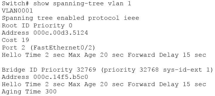
200-301 Part 03 Q01 021 The show spanning tree command is incorrect because it is not the correct syntax of a Cisco IOS command.
The show spantree and show spantree vlan commands are incorrect because these are CatOS commands, not Cisco IOS commands.
Objective:
LAN Switching Fundamentals
Sub-Objective:
Configure and verify Layer 2 protocols -
DRAG DROP
Click and drag the command(s) used to configure passwords on a Cisco router to their appropriate descriptions. (Not all options will be used.)
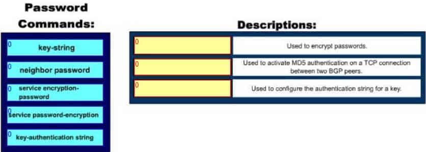
200-301 Part 03 Q02 022 Question 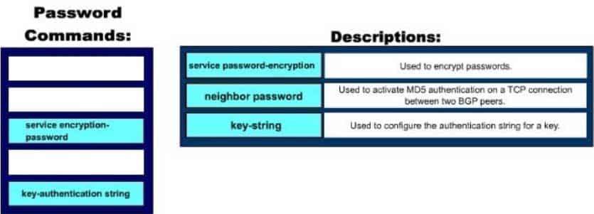
200-301 Part 03 Q02 022 Answer Explanation:
Following are the commands along with their descriptions:key-string: This command is used to configure the authentication string for a key.neighbor password: The neighbor password command is used to activate MD5 authentication on a TCP connection between two BGP peers. The complete syntax of this command is: neighbor { ip-address | peer-group-name } password string
service password-encryption: This command is used to encrypt passwords . When executed it will encrypt all text clear text passwords when they are created.
The other options offered are not valid commands.
Objective:
Infrastructure Security
Sub-Objective:
Configure, verify, and troubleshoot basic device hardening -
Which Enhanced Interior Gateway Routing Protocol (EIGRP) packet type is used for neighbor discovery?
- Hello
- Update
- Queries
- Replies
Explanation:
Hello packets are used for neighbor discovery. These are sent as multicasts and do not require an acknowledgement. Update packets are sent to communicate the routes used by a router to converge. When a new route is discovered or the convergence process is completed, updates are sent as multicast. During topology table synchronization, updates are sent as unicasts to neighboring peers.Query packets are sent when a router performs route computation and cannot find a feasible successor. These packets are sent to neighboring peers asking if they have a feasible successor to the destination network.
Reply packets are sent in response of a query packet. These are unicast and sent to the originator of the query.
Objective:
Routing Fundamentals
Sub-Objective:
Configure, verify, and troubleshoot EIGRP for IPv4 (excluding authentication, filtering, manual summarization, redistribution, stub) -
Which layer in the Open Systems Interconnection (OSI) model enables coding and conversion functions for application layer data?
- Presentation layer
- Session layer
- Application layer
- Physical layer
Explanation:
The Presentation layer in the OSI model enables coding and conversion functions for application layer data. Data formatting and encryption is done at this layer. The Presentation layer converts data into a format that can be accepted by the application layer. The Presentation layer is also known as the syntax layer, which provides translation between different data formats by using a common format. The Session layer in the OSI model does not enable coding and conversion functions for the application layer data. It is used to create, manage, and terminate sessions between communicating nodes. The session layer handles the service requests and service responses that take place between different applications.The Application layer in the OSI model does not enable coding and conversion functions for the application layer data. The application layer is responsible for interacting directly with the application, and provides application services, such as e-mail and File Transfer Protocol (FTP).
The Physical layer in the OSI model does not enable coding and conversion functions. The Physical layer consists of the hardware that sends and receives data on a carrier. The protocols that work at the Physical layer include Fast Ethernet, RS-232, and Asynchronous Transfer Mode (ATM). The Physical layer is the base layer in the OSI model.
The three remaining layers in the OSI model are the Transport, Network, and Data Link layers. The Transport layer is responsible for error-free and sequential delivery of data. This layer is used to manage data transmission between devices, a process known as flow control. The Transport layer protocols are Transmission Control Protocol (TCP) and User Datagram Protocol (UDP).
The Network layer is used to define the network address or the Internet Protocol (IP) address that is then used by the routers to forward the packets. The Data Link layer ensures reliable transmission of data across a network.
The seven layers of the OSI model are sequentially interconnected to each other. From the top to the bottom, the seven layers are:
Layer 7: Application
Layer 6: Presentation
Layer 5: Session
Layer 4: Transport
Layer 3: Network
Layer 2: Data Link
Layer 1: PhysicalObjective:
Network Fundamentals
Sub-Objective:
Compare and contrast OSI and TCP/IP models -
Which of these applications uses the IMAP protocol to transfer information between a server and a host?
- FTP
- Web browser
- Telnet
Explanation:
E-mail applications use Internet Message Access Protocol (IMAP) to retrieve messages from mail servers. IMAP differs from Post Office Protocol (POP3) in that IMAP allows the manipulation of email message as they remain on the email server, unlike POP3 in which the email can only be downloaded to the client. By default, IMAP uses TCP port 143. IMAP3 uses port 220.File Transfer Protocol (FTP) does not use IMAP. FTP transfers files from an FTP server to a client computer over the Internet or intranet. By default, FTP uses TCP port 21 to connect to the client system.A Web browser does not use IMAP. It uses Hyper Text Transmission Control Protocol (HTTP) to exchange information over the Internet. A Web browser provides access to the Internet through which a user can access text, images, and other information on a Web site. By default, HTTP uses TCP port 80 to connect to the client computer.
Telnet does not use IMAP. Telnet is an application that remotely accesses a computer for the purpose of executing commands. It uses TCP port 23 to connect to the remote computer.
Objective:
Network Fundamentals
Sub-Objective:
Compare and contrast TCP and UDP protocols -
Below is the output of the show ip route command from one of your routers:
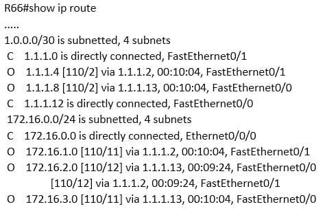
200-301 Part 03 Q06 023 What does the value 110 represent in the output?
- OSPF administrative distance
- EIGRP administrative distance
- OSPF cost
- EIGRP cost
Explanation:
The value of 110 represents the administrative distance of the route, which in this case was learned by OSPF. OSPF routes are always indicated by an O to the left of the route details. The two values in brackets in each route entry indicate the administrative distance on the left of the forward slash. The value to the right of the slash is the cost of the route. Therefore, [110/2] represents an administrative distance of 110 and a cost of 2.The value of 110 does not represent EIGRP administrative distance because the route was not learned from EIGRP. If it were, the route would have a D to the left of the route details. Moreover, the default administrative distance of EIGRP is 90, not 110.The values do not represent OSPF cost. The cost value is on the right side of the forward slash within the brackets in each route entry. For example, the route entry O 1.1.1.4 [110/2] via 1.1.1.2, 00:10:04, FastEthernet0/1 indicates an OSPF cost of 2.
The values do not represent an EIGRP cost. First, if it were an EIGRP route, the route would have a D to the left of the route details. Moreover, the cost value is located within the square brackets to the right of the forward slash in each route entry. The only cost values shown in the table are 2, 11, and 12.
Objective:
Routing Fundamentals
Sub-Objective:
Describe how a routing table is populated by different routing information sources -
With the following equipment list, which of the following network scenarios could be supported?
– Two IP subnets of 255.255.255.0
– Seven 48-port switches
– Two router interfaces- 300 workstations in a single broadcast domain, each workstation in its own collision domain
- 300 workstations, with 150 workstations in two broadcast domains and each workstation in its own collision domain
- 300 workstations, with 150 workstations in two broadcast domains and all workstations in the same collision domain
- 600 workstations, with 300 workstations in two broadcast domains and each workstation in its own collision domain
Explanation:
This equipment will support 300 workstations, with 150 workstations divided in two broadcast domains and each workstation in its own collision domain. Subnets with a 24-bit mask (255.255.255.0) yield 254 addresses in each network, so 150 is within those limits. Also, seven 48-port switches make 336 ports available. After subtracting out 2 ports per switch for connecting the switches to each other and the router ( a total of 14) that leaves 321 ports yielding 160 for each subnet ( with one left over) . Two subnets require two router interfaces, which are available in the scenario, and since switches are in use, each switch port is its own collision domain. This equipment will not support 300 workstations in a single broadcast domain with each workstation in its own collision domain. With a 24-bit mask, 300 workstations cannot be placed in a single subnet.This equipment will not support 300 workstations, 150 each in two broadcast domains and all workstations in the same collision domain. The 300 workstations cannot be placed in the same collision domain when using switches. If hubs were in use that would be possible, but not desirable.
This equipment will not support 600 workstations, 300 each in two broadcast domains; each workstation in its own collision domain. 600 workstations cannot be placed in two subnets when using the mask 255.255.255.0. Each subnet can only hold 254 workstations, not 300. Moreover, 300 workstations cannot be placed in the same collision domain when using switches. If hubs were in use that would be possible but not desirable.
Objective:
Network Fundamentals
Sub-Objective:
Describe the impact of infrastructure components in an enterprise network -
Which of the following is NOT a true statement regarding Virtual Private Networks (VPNs)?
- A VPN is a method of securing private data over public networks
- IPsec is a method for providing security over VPN
- Frame Relay is a Layer 3 VPN technology
- IPsec provides packet-level encryption
- A Cisco VPN solution provides increased security, reduced cost, and scalability
Explanation:
Frame Relay is a Layer 2 VPN technology, providing connectivity over switched carrier Wide Area Networks (WANs). Packets are encapsulated in Frame Relay frames, and assigned Data Link Connection Identifiers (DLCIs) to identify to the local Frame Relay switch the virtual circuit (VC) that the data should follow. A VPN is a method of securing private data over public networks (such as the Internet), so this is a true statement.IPsec is a security framework that provides security for data traveling over VPNs, so this is a true statement. It is an open standard protocol framework that is used to secure end-to-end communications.
IPsec allows for encryption at the packet level (Layer 3) when configured in tunnel mode, so this is a true statement.
VPN solutions such as those supported by Cisco ASA firewalls and Cisco integrated routers provide the following benefits:
– Lower desktop support costs
– Threat protection
– Flexible and cost-effective licensing
– Reduced cost and management complexityObjective:
WAN Technologies
Sub-Objective:
Describe WAN access connectivity options -
Which of the following IPV6 commands is used to define a static host name-to-address mapping in the host name cache?
- ipv6 host
- ipv6 unicast routing
- ipv6 neighbor
- ipv6 local
Explanation:
The ipv6 host command is used to define a static host name-to-address mapping in the host name cache, and is executed in global configuration mode. The ipv6 unicast-routing command is used to enable IPv6 forwarding on a router.There is no ipv6 local command. There is an ipv6 local pool command that can be used to define a prefix pool when using DHCPv6.
The ipv6 neighbor command is used to configure a static entry in the IPv6 neighbor discovery cache, which will enhance the neighbor discovery process that occurs with IPv6.
Objective:
Infrastructure Services
Sub-Objective:
Troubleshoot client connectivity issues involving DNS -
Which two statements are TRUE of synchronous serial ports? (Choose two.)
- These ports can be used to provide leased-line or dial-up communications.
- These ports do not support the High-Level Data Link Control (HDLC) encapsulation method.
- An AUI connector is used with serial ports.
- These ports can be used to configure high-speed lines (E1 or T1).
- An RJ-45 connector is used with serial ports.
Explanation:
Synchronous serial ports can be used to provide leased-line or dial-up communications, and these ports can be used to configure high-speed lines (E1 or T1). The following are also true of synchronous serial ports:
– With the help of synchronous serial lines, dialers can be configured, which are then used to support dial-on-demand routing.
– These ports are found on several serial network interface processors and cards. The option stating that synchronous serial ports cannot support High-Level Data Link Control (HDLC) encapsulation method is incorrect because HDLC is the default encapsulation method configured on serial interfaces.The option stating that an AUI connector is used with serial ports is incorrect because AUI is a connector used with Ethernet ports.
The option stating that an RJ-45 connector is used with serial ports is incorrect because RJ-45 and RJ-48 connectors are used with ISDN BRI connections.
Objective:
WAN Technologies
Sub-Objective:
Describe WAN access connectivity options -
Refer to the following sample output:

200-301 Part 03 Q11 024 Which Cisco Internetwork Operating System (IOS) command produces this output?
- show interfaces
- show interfaces summary
- show interfaces serial fast-ethernet
- show interfaces fast-ethernet 0/0
Explanation:
The show interfaces summary command will produce the given output. This command provides a summarized view of all interfaces configured on a device. The show interfaces command is incorrect because this command does not produce the displayed output. This command is used to view information regarding statistics for specific interfaces. Without specifying an interface, a section for each interface will display, as in the example below for FastEthernet0:
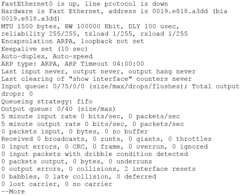
200-301 Part 03 Q11 025 The show interfaces serial fast-ethernet command is incorrect because this is not a valid Cisco IOS command.
The show interfaces fast-ethernet 0/0 command is incorrect. Although it produces similar output, that output only relates to the FastEthernet 0/0 interface. An example of this output follows:
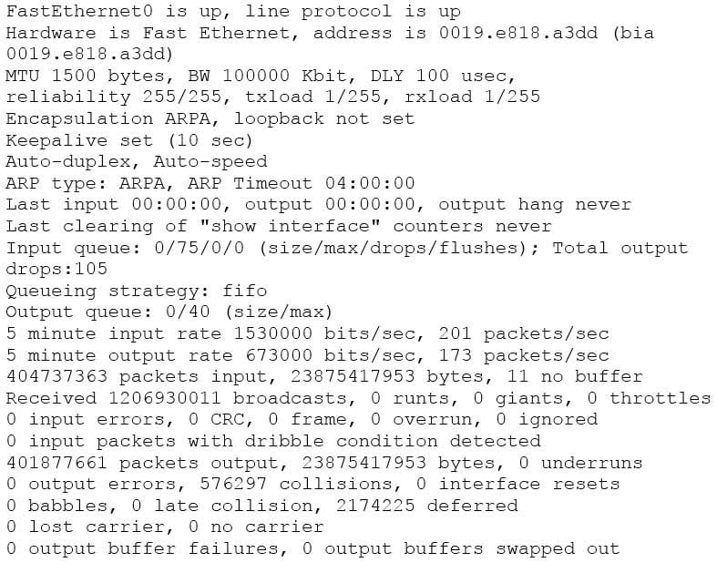
200-301 Part 03 Q11 026 Notice that the line of output that says FastEthernet0 is up, line protocol is up indicates that Layers 1 to 3 of the OSI Model are functioning correctly. Also, in the lower portion, there are no values in the error counters such as input errors, output errors, and so on. Finally, make note in line 8 where the interface is set to autosense both the duplex and the speed. Duplex and speed must be in agreement between the NIC on the host and the switch port.
Objective:
Routing Fundamentals
Sub-Objective:
Troubleshoot basic Layer 3 end-to-end connectivity issues -
Which of the following is NOT a VLAN Trunking Protocol (VTP) mode of operation?
- client
- server
- virtual
- transparent
Explanation:
Virtual is not a valid VTP mode of operation. There are three different VTP modes of operation: client, server, and transparent. In client mode, a switch can synchronize VLAN information with the domain and forward advertisements. However, VLANs cannot be created, deleted, or modified from a switch in client mode. Also, a client mode switch does not save VLAN information in non-volatile Random Access Memory (NVRAM). It is stored in Flash in a file called vlan.dat.In server mode, a switch synchronizes the VLAN information with the domain, sends and forwards advertisements, and can create, delete, or modify VLANs. In server mode, VLAN information is stored in Flash in a file called vlan.dat.
In transparent mode, a switch does not synchronize its VLAN configuration with the domain, but it forwards advertisements. VLANs can be created, deleted, or modified locally and VLAN configuration is saved in both the running-config file in RAM and in flash in a file called vlan.dat.
Objective:
LAN Switching Fundamentals
Sub-Objective:
Configure, verify, and troubleshoot VLANs (normal/extended range) spanning multiple switches -
A host is powered up, but the connected switch port does not turn amber or green.
Which of the following methods would you use to troubleshoot the situation? (Choose three. Each answer is a complete solution.)
- Ensure the switch is powered up.
- Reinstall Windows on the workstation.
- Reseat the cable.
- Ensure that the cable is straight-through.
- Ensure that the cable is crossover.
Explanation:
A black or unlit switch port LED is symptomatic of a Layer 1 problem. The port LED should first turn amber and then turn solid green when a host is powered up. The amount of time it takes to turn solid green will depend on the Spanning Tree Protocol configuration. If the LED is unlit, you should ensure that the switch is powered up and that a straight-through cable is used to connect a switch port to a host, such as a workstation or a printer. If the switch is powered up and a straight-through cable is used, reseat the cable to ensure a firm connection. Reinstalling Windows on the workstation will not help because this is a Layer 1 problem having to do with the switch having power or the use of proper cabling.You should not ensure that the cable is crossover, because straight-through (patch) cables are used to connect switch ports to hosts.
Objective:
LAN Switching Fundamentals
Sub-Objective:
Troubleshoot interface and cable issues (collisions, errors, duplex, speed) -
DRAG DROP
Click and drag the RSTP port state on the left to its matching equivalent STP role, on the right. RSTP port states may be used more than once, and it may not be necessary to use all RSTP port states.

200-301 Part 03 Q14 027 Question 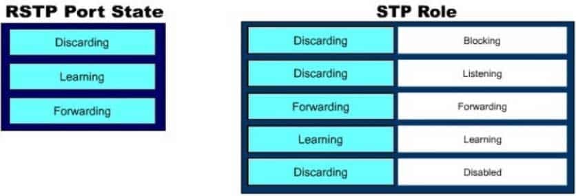
200-301 Part 03 Q14 027 Answer Explanation:
Rapid Spanning Tree Protocol (RSTP) was developed to reduce the high convergence times required in Spanning Tree Protocol (STP), and introduces the alternate port and backup port. RSTP is an Institute of Electrical and Electronics Engineers (IEEE) standard, 802.1w, and is interoperable with 802.1d (STP). There are fewer transitional states used in RSTP than STP. In RSTP, there are only Forwarding, Learning, and Discarding. The three states are defined as follows:
– Forwarding – the state of all root ports and designated ports. The port is passing traffic.
– Learning – the state of a port that was formerly discarding but due to a change in the topology (link down) it has transitioned to learn its new state. The port could return to discarding or move to forwarding depending on the new topology needs
– Discarding – the state of all non-root and non- designated ports. The port is not passing traffic to prevent potential switching loops.RSTP can reconfigure the spanning tree in less than a second, compared to the 50 seconds that STP may take. This is achieved through having fewer transition states, the use of alternate and backup ports, and faster transitions.Objective:
LAN Switching Fundamentals
Sub-Objective:
Configure, verify, and troubleshoot STP protocols -
Which of the following commands will enable a global IPv6 address based on the Modified EUI-64 format interface ID?
- ipv6 address 5000::2222:1/64
- ipv6 address autoconfig
- ipv6 address 2001:db8:2222:7272::72/64 link-local
- ipv6 enable
Explanation:
To configure the interface to create a global IPv6 address based on the Modified EUI-64 format interface ID, you must enable stateless autoconfiguration. In stateless autoconfiguration, the interface will receive the network prefix from the router advertisement (RA) and generate a full IPv6 address by spreading the 48-bit MAC address of the interface across 64 bits to complete the address. This can all be done simply by executing the ipv6 address autoconfig command at the interface configuration prompt. The command ipv6 address 5000::2222:1/64 is used to manually assign a full IPv6 address to the interface without using stateless autoconfiguration or the eui-64 keyword to manually specify the first 64 bits and allow the last 64 bits to be generated from the MAC address of the interface.The command ipv6 address 2001:db8:2222:7272::72/64 link local is used to configure a link-local address manually without allowing the system to generate one from the MAC address, which is the default method.
The command ipv6 enable is used to allow the system to generate a link-local address from the MAC address. Because this is the default behavior, the command is not required if any other ipv6 commands have been issued. Regardless of how many manual IPv6 addresses you configure, a link local address is always generated by default.
Objective:
Network Fundamentals
Sub-Objective:
Configure, verify, and troubleshoot IPv6 addressing -
Which of the following commands is used to verify the link-local, global unicast, and multicast addresses of an IPv6 router?
- show ipv6 neighbors (only link-local addresses)
- show ipv6 route
- show ipv6 protocols
- show ipv6 interface
Explanation:
The show ipv6 interface command is used to verify the link-local, global unicast, and multicast addresses assigned to an IPv6-enabled router interface. The show ipv6 interface command displays information regarding that interface, such as the physical state, MTU, and IPv6 enable/disable state. Here is the partial output of the show ipv6 interface command on an IPv6-enabled router named rtrA:
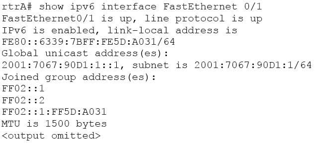
200-301 Part 03 Q16 028 In the sample output, you can see that the Fa0/1 interface of rtrA has the link-local address FE80::6339:7BFF:FE5D:A031/64 and the global unicast address 2001:7067:90D1:1::1. The global unicast address is not in EUI-64 format because when the ipv6 address command was issued, the eui64 keyword was not used. If the EUI-64 format had been specified with the eui64 keyword, the global unicast address would have been 2001:7067:90D1:1:6339:7BFF:FE5D:A031.
An IPv6-enabled interface has not only a link-local and global unicast address, but also one or more multicast addresses. A multicast address is an IPv6 address that has the prefix FF00::/8. These addresses are assigned to interfaces of different nodes such that they appear as a logical group. This implies that when a packet is destined for a multicast address, that packet is delivered to all the interfaces that have the same multicast address. The various multicast groups are as follows:
– FF02::1 Indicates the group of all the nodes on the local segment
– FF02::2 Indicates the group of all the routers on the local segment
– FF02::1:FF00:0/104 Indicates a solicited-node multicast group for every unicast or anycast address assigned to the interfaceYou can also notice in the sample output that the Fa0/1 interface belongs to three multicast groups: FF02::1, FF02::2, and FF02::1:FF5D:A031. The first two multicast groups refer to the all-host and all-router multicast groups, respectively. The third group, FF02::1:FF5D:A031, is the solicited-node multicast address. This address is created for every unicast or anycast address. A solicited-node multicast address is determined by assigning the least significant 24 bits of the unicast address to the least significant 24 bits of the FF02::1:FF00:0 address.
The show ipv6 neighbors command displays the link-local /global unicast addresses of the neighbors, including other information such as state and the next-hop interface.
The show ipv6 route command is used to view the IPv6 routing table on the router. This command displays the prefixes, administrative distance, metric, and next-hop addresses for various IPv6 networks.
The show ipv6 protocols command is used to view the active routing protocols for IPv6 on the router. This command shows the interfaces, redistribution status, and summarization status about each of the routing protocols enabled on the router.
Objective:
Network Fundamentals
Sub-Objective:
Configure, verify, and troubleshoot IPv6 addressing -
Which type of Category 5 unshielded twisted-pair (UTP) cable is used to work as a trunk between two switches?
- RJ-45 straight-through
- RJ-41 crossover
- RJ-11 straight-through
- RJ-45 crossover
Explanation:
An RJ-45 crossover cable connects two switches. To act as a trunk a trunking protocol such as ISL or 802.1q must be configured on the link. . A trunk is a connection between two switches that is used to carry traffic from multiple VLANs. In general, the rule to follow when choosing between a straight-through and a crossover cable is:
– When connecting like devices (i.e. router to router, switch to switch), use a crossover cable.
– When connecting dissimilar devices (i.e. switch to router), use a straight-through cable.The one exception to this rule is when connecting a computer NIC to a router, in which case a crossover cable is used. Be aware, however, that many devices, including network cards in computers, now have the ability to sense automatically when they are connected to a like device and adapt to the connection, making crossover cables unnecessary in those situations.
You should not choose an RJ-45 straight-through cable. The cable type to be used depends on the circuit connection of the hardware. To connect two switches, a crossover cable is required. The difference between a straight-through cable and a crossover cable lies in the location of the wire termination on the two ends of an RJ-45 cable. If the UTP cable wire connects Pin 1 of one side to Pin 1 of other side and Pin 2 to 2 through all eight pins of the RJ 45 connector, the cable is said to be straight-through. On the other hand, if Pin 1 of one side of an RJ-45 cable connects to Pin 3 of the other end, and Pin 2 connects to Pin 6 of the other end, it is known as a crossover cable. A straight-through cable is used to connect a computer’s network interface card (NIC) to a hub or switch.
You should not choose an RJ-41 crossover cable. RJ-41 is a single-line universal data jack normally associated with fixed-loss loop (FLL) or programmed (P) modems. It is not used between switches.
You should not choose an RJ-11 straight-through cable type. RJ-11 UTP cables have four pins and are used to connect voice instruments. RJ-11 UTP cables are not intended for connecting computers and transferring data. They are commonly used for telephones and modems.
Note: Cisco switches have an auto-mdix feature that notices when the wrong cabling pinouts are used, and readjusts the switch’s logic so that the cable will work.
Objective:
Network Fundamentals
Sub-Objective:
Select the appropriate cabling type based on implementation requirements -
A router is running a classful routing protocol. Which command will enable this router to select a default route when routing to an unknown subnet of a network for which it knows the major network?
- ip classless
- no ip classless
- auto-summary
- no auto-summary
Explanation:
The ip classless command causes a routing protocol to change its default behavior of discarding any traffic that is bound for unknown subnets of a known classful network. If the command is enabled, the router tries to match the most number of bits possible against the route in its routing table. Alternatively, the router will use the default route rather than dropping the packet. For an example of this behavior, examine the diagram below. The ip route 0.0.0.0 0.0.0.0 serial 0/0 command has been issued on Router B. If the 25.1.6.0/24 network is unknown to Router B, then under normal circumstances, Router B would NOT use its configured default route. Instead, it would drop any packets addressed to that unknown network, because when a router knows a route to a major classful network or its subnets (in this case, 25.1.5.0/30 and 25.1.1.0/24), it will not use a statically configured default route to forward traffic to an unknown subnet of that network (in this case 25.1.6.0/24). In the scenario described in the diagram, Router B will drop the packet. However, if the ip classless command has been executed, it will use the default route and send the traffic to Router A.
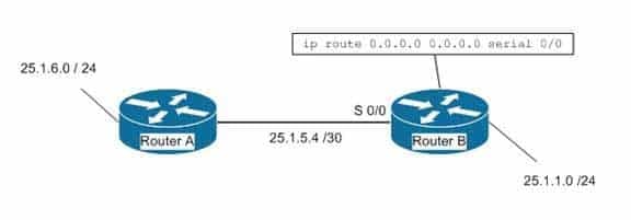
200-301 Part 03 Q18 029 The ip classless command is a global configuration mode command enabled by default in Cisco IOS version 12.0 and later. If the default route is learned from IS-IS or OSPF, as opposed to being statically configured as in the above example, the ip classless command is not necessary for the router to use the default route.
The no ip classless command on routers will disable the forwarding of packets destined to an unknown subnet of a known classful network. Therefore, it is an incorrect option.
The auto-summary command is used to allow automatic summarization of subnet routes into network-level routes. This is a command executed in router configuration mode.
Classless routing protocols such as Routing Information Protocol version 2 (RIPv2) and Enhanced Interior Gateway Routing Protocol (EIGRP) perform automatic route summarization at classful boundaries. The no auto-summary command is used to turn off this route summarization.
Objective:
Routing Fundamentals
Sub-Objective:
Configure, verify, and troubleshoot IPv4 and IPv6 static routing -
Which Cisco IOS command is used to configure encapsulation for a PPP serial link on a Cisco router?
- encapsulation ppp
- encapsulation ip ppp
- ip encapsulation ppp
- encapsulation ppp-synch
Explanation:
PPP is a Layer 2 protocol encasulation type that supports both synchronous and asynchronous circuits and provides built-in security mechanaims. The encapsulation ppp interface configuration mode command is used to configure encapsulation for a PPP (Point to Point Protocol) serial link on a Cisco router. PPP encapsulation provides for router-to-router and host-to-network connections over both synchronous and asynchronous circuits. Serial links are configured to use Cisco High Level Data Link Control (HDLC) encapsulation, by default, on Cisco routers. The Cisco version of HDLC is incompatible with the industry standard version used on other router brands because it contains a type field that identifies the underlying network protocol being encapsulated by HDLC. This is a beneficial feature of Cisco HDLC but makes it incompatible with other router brands. For this reason, a Cisco router that is going to be connected to a non-Cisco router should be configured to use PPP instead of the default. The encapsulation ppp interface configuration mode command will do this. If you set one of the routers for PPP and leave the other router at the default encapsulation for a serial connection, the connection will fail due to incompatible encapsulation.You would use the show run command to verify matching encapsulation types. In the partial output of the show run command for two routers shown below, it can be seen that although one of the routers has the encapsulation ppp command in its configuration, the other does not. The absense of the encapsulation ppp command means that the default HDLC is being used. This incompatibility will cause both routers to report a serial interface up, line protocol down condition since the connection is live, but the Layer 2 framing is misconfigured.

200-301 Part 03 Q19 030 If authentication between the routers is also required, the authentication pap, authentication ms-chap, or authentication chap commands could be used to apply Password Authentication Protocol (PAP), Microsoft Challenge Authentication Protocol (MS-CHAP), or Challenge Authentication Protocol (CHAP) authentication to the connection, respectively.
A full configuration of a serial link for using PPP with authentication is as shown below:
Router1(config)#interface Serial0
Router1(config-if)#encapsulation ppp
Router1(config-if)#ppp authentication pap
Note above that the third line enables PAP authentication, which is not secure. Alternately, you can use CHAP authentication (which is secure) with the ppp authentication chap command. Regardless of which authentication mechanism you choose, these authentication commands will only be accepted on an interface where PPP encapsulation has been enabled, which rules out any non-serial interfaces.
The third type of encapsulation that can be configured on a serial WAN link is Frame Relay, which can be selected with the encapsulation frame relay command under the interface.
In summary, the three encapsulation types available for WAN serial links are PPP, HDLC, and Frame Relay. The command for each is as follows, executed under the interface configuration prompt:
encapsulation ppp
encapsulation hdlc
encapsulation frame relayAll other options are invalid commands.
Objective:
WAN Technologies
Sub-Objective:
Configure and verify PPP and MLPPP on WAN interfaces using local authentication -
A user in your network is having trouble accessing resources and the Internet. You decide to examine the partial output of the ipconfig/all command on his machine. The output is shown below:
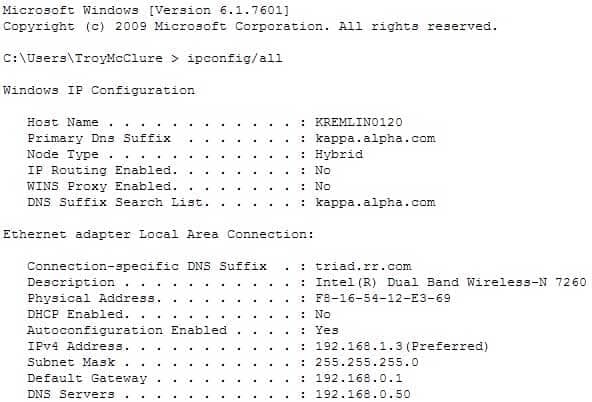
200-301 Part 03 Q20 031 Which of the following statements describes the user’s problem?
- The default gateway address is incorrect
- The IP address of the device is incorrect
- There is no DNS server configured
- IP routing is not enabled
Explanation:
The IP address of the device is incorrect. It is not in the same subnet as the default gateway address. While it is possible that the default gateway address is incorrect, that is not as likely a reason, given the fact that the DNS server is also in the same IP subnet as the default gateway. There is a DNS server configured and its IP address is 192.168.0.50. If a DNS server were not configured, this user would be unable to access the Internet, even if all IP addressing problems were resolved.IP routing is NOT enabled. However, it is not required to be enabled because this device is not acting as a router. The device does not need IP routing enabled to access resources and the Internet if all other IP addressing issues are resolved.
Objective:
Infrastructure Services
Sub-Objective:
Describe DNS lookup operation