200-301 : Cisco Certified Network Associate (CCNA) : Part 05
-
Which of the following is NOT an advantage of static routes over dynamic routing protocols?
- Routing protocol overhead is not generated by the router.
- Bandwidth is not consumed by route advertisements between network devices.
- Static routes are easier to configure and troubleshoot than dynamic routing protocols.
- Static route configuration is more fault tolerant than dynamic routing protocols.
Explanation:
Static route configuration is NOT more fault tolerant than dynamic routing protocols. The following lists the true advantages of static routes over dynamic routing protocols:
– Routing protocol overhead is not generated by the router.
– Bandwidth is not consumed by route advertisements between network devices.
– Static routes are easier to configure and troubleshoot than dynamic routing protocols.
– Router resources are more efficiently used.
– Network security is increased by using static routes. The following are disadvantages of static routes:
– Static routes are not recommended for large networks because static routes are manually configured on the router. Therefore, maintaining routes in a timely manner is nearly impossible.
– Static route configuration is not fault tolerant without configuring multiple static routes to each network with varying administrative distances.All other options are incorrect because these are the advantages of static routes over dynamic routing protocols.
Objective:
Routing Fundamentals
Sub-Objective:
Compare and contrast static routing and dynamic routing -
Which settings represent the proper BITs per second, data bits, and parity settings for a HyperTerminal session to the router?
- 19200,8,none
- 9600,8,none
- 9600,8, even
- 19200,8,even
Explanation:
When setting up a HyperTerminal session to either a router or a switch, the proper settings must be enabled or the connection will not work. The proper settings are 9600 bits per second, 8 data bits, and none in the parity box. The HyperTerminal application is provided on Windows operating systems up to Windows XP. The path to the tool is Start > Programs > Accessories > Communications > HyperTerminal. For later Windows operating systems, a HyperTerminal program must be downloaded and installed. After opening the tool, you will name the connection and select a COM port if you want to use a port other than the default, which is the serial port to which the console cable is connected. You will then be presented with the following box:
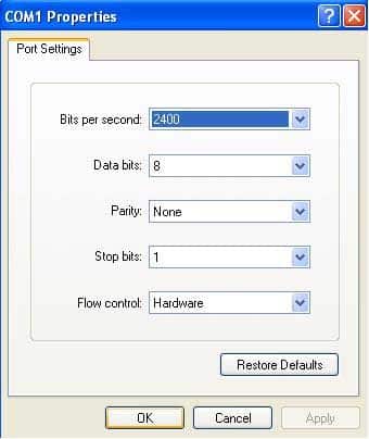
200-301 Part 05 Q02 049 The settings should reflect 9600 bits per second, 8 data bits, no parity, 1 stop bit, and no flow control, as illustrated in this graphic:
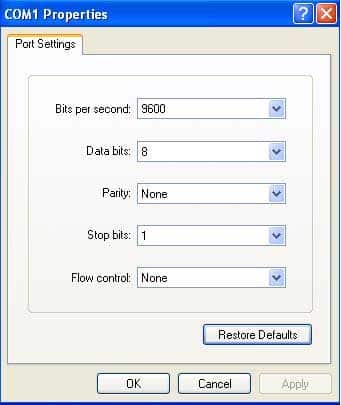
200-301 Part 05 Q02 050 All other options include incorrect settings in at least one category.
Objective:
Infrastructure Management
Sub-Objective:
Configure and verify device management -
Which command would be used to establish static translation between an inside local address 192.168.144.25 and an inside global address 202.56.63.102?
-
router(config)#ip nat inside source static 192.168.144.25 202.56.63.102 -
router(config)#ip source nat inside static local-ip 192.168.144.25 global-ip 202.56.63.102
-
router(config)#ip nat static inside source 192.168.144.25 202.56.63.102
-
router(config)#ip nat inside static source 192.168.144.25 202.56.63.102
Explanation:
To establish a static translation between an inside local address 192.168.144.25 and an inside global address 202.56.63.102, you would use the ip nat inside source static 192.168.144.25 202.56.63.102 command executed in global configuration mode. The correct format of the command is:ip nat inside source static local-ip global-ip
This static configuration can be removed by entering the global no ip nat inside source static command.
Simply executing the ip nat inside source command will not result in NAT functioning. The NAT process also has to be applied correctly to the inside and outside interfaces. For example, if, in this scenario the Fa0/0 interface hosted the LAN and the S0/0 interface connected to the Internet the following commands would complete the configuration of static NAT.
Router(config)#interface F0/0
Router(config-if)#ip nat inside
Router(config-if)#exit
Router(config)#interface S0/0
Router(config-if)#ip nat outside
The other options are incorrect because they are not valid Cisco IOS configuration commands. They all contain syntax errors.
Objective:
Infrastructure Services
Sub-Objective:
Configure, verify, and troubleshoot inside source NAT -
-
Which WAN switching technology is used by Asynchronous Transfer Mode (ATM)?
- cell-switching
- virtual switching
- circuit-switching
- packet switching
Explanation:
Cell switching is used by Asynchronous Transfer Mode (ATM). ATM is an International Telecommunication Union-Telecommunications (ITU-T) standard for transmission of data, voice, or video traffic using a fixed size frame of 53 bytes, known as cells. Out of these 53 bytes, the initial five bytes are header information and the remaining 48 bytes are the payload. The term virtual switching is incorrect because it is not a valid WAN switching technology.Circuit switching dynamically establishes a virtual connection between a source and destination. The virtual connection cannot be used by other callers unless the circuit is released. Circuit switching is the most common technique used with the Public Switched Telephone Network (PSTN) to make phone calls. The dedicated circuit is temporarily established for the duration of the call between caller and receiver. Once the caller or receiver hangs up the phone, the circuit is released and is made available to other users.
Packet switching is also used for data transfer but not in an ATM network. With packet switching, the data is broken into labeled packets and is transmitted using packet-switching networks. The Internet and LAN communications use packet switching.
Objective:
WAN Technologies
Sub-Objective:
Describe WAN access connectivity options -
You are configuring a serial link between a Cisco router and a router produced by another vendor.
What would be the advantages of using Point to Point Protocol (PPP) over High Level Data Link Control (HDLC) in this scenario?
- HDLC has a proprietary “type” field that may be incompatible with equipment from other vendors.
- HDLC is not available on non-Cisco routers.
- PPP is faster.
- PPP performs error checking.
Explanation:
High Level Data Link Control (HDLC) has a proprietary “type” field that may be incompatible with equipment from other vendors. It is recommended that PPP always be used when combining equipment from multiple vendors because this Data Link layer WAN protocol is an industry standard. PPP is implemented in the same manner on all PPP-capable equipment. HDLC is available on non-Cisco routers. However, the Cisco implementation has a “type” field that may prevent the connection from working.PPP is not faster than HDLC.
PPP performs error checking, but so does HDLC.
Objective:
WAN Technologies
Sub-Objective:
Describe WAN access connectivity options -
You would like for Router25 in your OSPF network to become the DR. You execute the show ip ospf interface command, receiving the output shown below.

200-301 Part 05 Q06 051 You assign an IP address of 192.168.5.6 to the Ethernet1 interface of Router25 and enable the interface. However, Router25 does NOT become the designated router.
What additional command must you execute to cause Router25 to become the DR?
-
Router25(config-router)# network 192.168.5.0 0.0.0.255 area 0 -
Router25(config-router)# network 192.168.5.0 0.0.0.255 area 1
-
Router25(config-router)# network 192.168.5.0 255.255.255.0 area 0
-
Router25(config)# network 192.168.5.0 0.0.0.255 area 0
Explanation:
The command Router25(config-router)# network 192.168.5.0 0.0.0.255 area 0 must be executed to enable Router25 to become the DR. For an interface to be considered in the DR election, it must be advertised in OSPF. Otherwise, it is not participating in OSPF routing and you may be faced with the situation illustrated by the output of the shown ip ospf interface command below:

200-301 Part 05 Q06 052 The RID of Router25, 225.16.33.4, is higher than that of the current DR, which has an RID of 172.16.10.1. Despite that fact, Router 25 did not become the DR because the 225.0.0.0 network has not been advertised. This could be verified by executing the show ip protocols command as shown below:
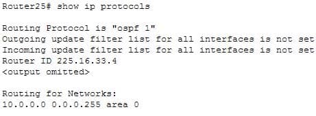
200-301 Part 05 Q06 053 As only the 10.0.0.0 network is being advertised, the 225.16.33.4 IP address will not be a factor in the DR election.
The command Router25(config-router)# network 192.168.5.0 0.0.0.255 area 1 is incorrect because it references area 1 instead of area 0, which is the area in use in this scenario.
The command Router25(config-router)# network 192.168.5.0 255.255.255.0 area 0 is incorrect because it uses a regular mask instead of a wildcard mask. Network commands in OSPF must use a wildcard mask.
The command Router25(config)# network 192.168.5.0 0.0.0.255 area 0 is incorrect because it is executed at the global configuration, router25(config)#, prompt rather than the OSPF configuration prompt, router25(config-router)#.
Objective:
Routing Fundamentals
Sub-Objective:
Configure, verify, and troubleshoot single area and multi-area OSPFv2 for IPv4 (excluding authentication, filtering, manual summarization, redistribution, stub, virtual-link, and LSAs) -
-
On Cisco switches, what is the correct order of port transition through the Spanning Tree Protocol (STP) states?
- learning, listening, blocking, forwarding
- listening, blocking, forwarding, learning
- blocking, learning, forwarding, listening
- blocking, listening, learning, forwarding
Explanation:
There are five states in STP transition:
– Blocking
– Listening
– Learning
– Forwarding
– DisabledAfter STP initialization, a port moves from blocking to listening, then to learning, and finally into forwarding state. In case of any errors or exceptions, a port may enter into a disabled state directly from any of the other four states. Once STP has fully converged, all ports on all switches will be in either a forwarding state or a blocking state. All other port states are transitioning states between blocking and forwarding.When STP is initialized, all ports start in the blocking state to prevent bridge loops. If a switch determines that a blocking port must transition to a forwarding state, the blocked port will first move into a listening state, where it begins sending Bridge Protocol Data Units (BPDUs). Next, the port will transition to a learning state, which allows it to populate its Media Access Control (MAC) address table with addresses learned on the port, but it does not yet forward data frames. Finally, it moves into the forwarding state, where the port is capable of sending and receiving data. The switch only learns MAC addresses during the learning and forwarding states.
Objective:
LAN Switching Fundamentals
Sub-Objective:
Configure, verify, and troubleshoot STP protocols -
Examine the diagram below and assume that routing is configured properly.
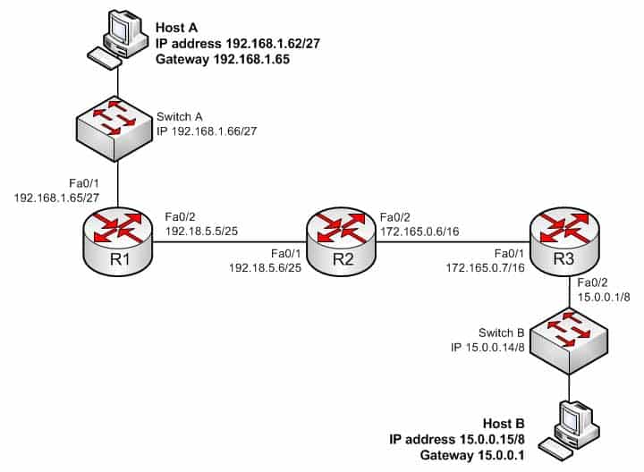
200-301 Part 05 Q08 054 Why is Host A unable to ping Host B?
- The IP address of Switch A is incorrect
- The IP address of Switch A is incorrect
- The IP address of Host A is incorrect
- The Fa0/2 and Fa0/1 interfaces on R1 and R2 are not in the same subnet
Explanation:
The IP address of Host A is incorrect. The Fa0/1 interface on R1 (Host A’s default gateway) is in the 192.168.1.64/27 network, and Host A’s IP address is in the 192.168.1.32/27 network. With a 27-bit mask against the 192.168.1.0 classful network, the resulting subnets are:192.168.1.0
192.168.1.32
192.168.1.64
192.168.1.92And so it would continue, increasing the fourth octet in intervals of 32. By only going this far we can see that they are in different subnets.
The IP address of Switch A is correct for its subnet because it needs to be in the same subnet as the Fa0/1 interface on R1. Even if it were incorrect or missing altogether it would have no impact on Host A. Switches merely switch frames based on MAC addresses and only need an IP address for management purposes.
The gateway address of Host B is correct. It is in the same subnet (15.0.0.0/8) with the Fa0/2 interface on R2, its gateway.
The Fa0/2 and Fa0/1 interfaces on R1 and R2 are in the same subnet. Using a 25-bit mask against the 192.18.5.0/24 classful network yields the following subnets:
192.18.5.0
192.168.5.128Both router interfaces in question are in the 192.18.5.0 subnet.
Objective:
Network Fundamentals
Sub-Objective:
Configure, verify, and troubleshoot IPv4 addressing and subnetting -
R1 and R2 are connected as shown in the diagram and are configured as shown in output in the partial output of the show run command.
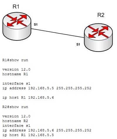
200-301 Part 05 Q09 055 The command ping R2 fails when executed from R1. What command(s) would allow R1 to ping R2 by name?
-
R1(config)#int S1

R1(config-if)#no ip address 192.168.5.5

R1(config-if)# ip address 192.168.5.9 255.255.255.252
-
R1(config)#no ip host R1 R1(config)# ip host R2 192.168.5.6 255.255.255.252 -
R1(config)#no hostname R2

R1(config)# hostname R1
-
R2(config)#int S1

R1(config-if)#no ip address 192.168.5.5

R1(config-if)# ip address 192.168.5.9 255.255.255.0
Explanation:
Both routers have been configured with the ip host command. This command creates a name to IP address mapping, thereby enabling the pinging of the device by address. On R1, the mapping is incorrect and needs to be corrected. Currently it is configured as ip host R1 192.168.5.6. It is currently mapping its own name to the IP address of R2.To fix the problem, you should remove the incorrect IP address mapping and create the correct mapping for R2, as follows:R1(config)#no ip host R1 R1(config)# ip host R2 192.168.5.6 255.255.255.252
Once this is done, the ping on R2 will succeed.
The IP address of the S1 interface on R1 does not need to be changed to 192.168.5.9 /30. In fact, if that is done the S1 interface on R1 and the S1 interface in R2 will no longer be in the same network. With a 30-bit mask configured, the network they are currently in extends from 192.168.5.4 – 192.168.5.7. They are currently set to the two usable addresses in that network, 192.168.5.5 and 192.168.5.6.
The hostnames of the two routers do need to be set correctly using the hostname command for the ping to function, but they are correct now and do not need to be changed.
The subnet mask of the S1 interface on R2 does not need to be changed to 255.255.255.0. The mask needs to match that of R1, which is 255.255.255.252.
Objective:
Infrastructure Services
Sub-Objective:
Troubleshoot client connectivity issues involving DNS -
-
You are attempting to add an IP address to an interface on a router with which you are unfamiliar. You type the following command and receive the following error:
Router78(config)#interfce Serial0
^
%invalid input detected at '^' marker.
Which of the following could be a reason for receiving this message?
- the command syntax is incorrect
- the interface type does not exist on this router
- the command is entered at the wrong prompt
- the interface is configured already
Explanation:
The command has a syntax error. The word interface is misspelled as indicated by the marker. The interface type may not exist on the router, but that is not the problem with this specific error message. If you attempt to access an interface that is not present on the router, it will elicit this same message, but the marker will be placed at the beginning of the interface type as shown below. The interface information is in lines 14-19.Router78(config)#interface Serial0 %invalid input detected at '^' marker.
When you are unfamiliar with a router, it is best to execute the show version command, which will indicate the type and number of interfaces on the router as shown below:
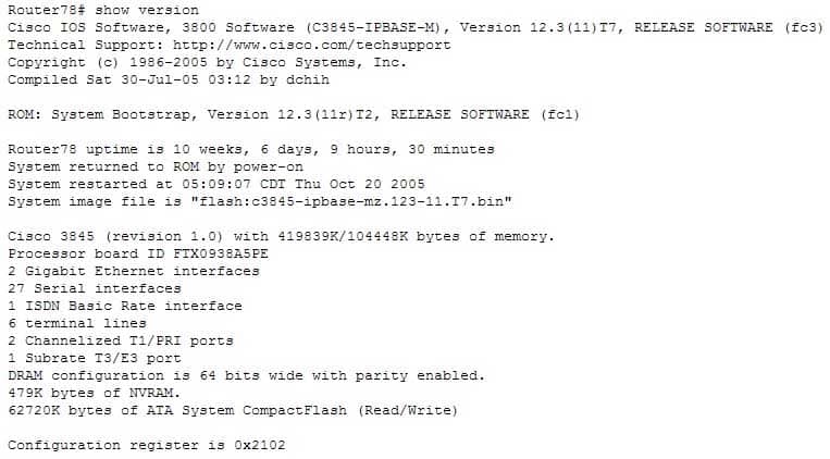
200-301 Part 05 Q10 056 The command is not entered at the wrong prompt. It should be entered at the global configuration prompt.
If the interface were already configured, it would still allow you to access the interface and make changes.
Objective:
LAN Switching Fundamentals
Sub-Objective:
Troubleshoot interface and cable issues (collisions, errors, duplex, speed) -
Which three statements are TRUE regarding Network Address Translation (NAT)? (Choose three.)
- It connects different Internet Service Providers (ISPs).
- It can act as an address translator between the Internet and a local network.
- It conserves IP addresses.
- It creates additional IP addresses for the local network.
- It helps the local network connect to the Internet using unregistered IP addresses.
Explanation:
NAT can act as an address translator between the Internet and the local network, conserve Internet Protocol (IP) addresses, and help the local network connect to the Internet using unregistered IP addresses. The following statements are also TRUE regarding NAT:
– It can be used to present a single address for the entire network to the outside world when used in dynamic mode.
– It enhances network security by not disclosing the internal network addresses to the outside world.It is not true that NAT connects different Internet Service Providers (ISPs). A gateway is used to connect different ISPs.
It is not true that NAT creates additional IP addresses for the local network. It only enables the use of unregistered addresses on the local area network.
Objective:
Infrastructure Services
Sub-Objective:
Configure, verify, and troubleshoot inside source NAT -
What is the default sequence in which a router searches for the Internetwork Operating System (IOS) image upon power on?
- TFTP, Flash, ROM
- ROM, Flash, TFTP
- Flash, TFTP, ROM
- Flash, TFTP, NVRAM
- NVRAM, Flash, TFTP
Explanation:
The default sequence in which a router searches for the IOS image is in Flash memory, on a Trivial File Transfer Protocol (TFTP) server, and in read-only memory (ROM). The router will first search for the IOS image in the Flash memory. If there is no image in the Flash, the router will try to contact a TFTP server. If the router cannot find the IOS image on the TFTP server, it will load a limited version from the ROM. The sequence that begins with TFTP and the sequence that begins with ROM are both incorrect sequences because the router will begin searching for the IOS image in Flash memory.The sequences that include Non-volatile random access memory (NVRAM) are both incorrect because a router does not store the IOS image in NVRAM. The startup configuration is stored in NVRAM.
Objective:
Infrastructure Management
Sub-Objective:
Perform device maintenance -
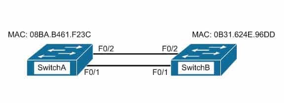
Which switch port will be in a blocking state? (Click the Exhibit(s) button to view the switch port diagram.)
200-301 Part 05 Q13 057 - SwitchA Fa0/1
- SwitchA Fa0/2
- SwitchB Fa0/1
- SwitchB Fa0/2
Explanation:
SwitchB will be forwarding on F0/1, and blocking on F0/2.SwitchA will become the STP root bridge due to its lower MAC address. All ports on the root bridge will become designated ports in a forwarding state. SwitchB has redundant connectivity to the root bridge, and must block one of its interfaces to prevent a switching loop. STP will use its operations to determine which of the redundant interfaces on SwitchB to block to prevent a switching loopBoth interfaces are the same speed (FastEthernet), and thus their cost to the root is the same.
Finally, the interface with the lowest number will become the forwarding port. F0/1 has a lower port number than F0/2, so F0/1 becomes a forwarding port, and F0/2 becomes a blocking port.
Note: Unlike STP, Rapid Spanning Tree Protocol (RSTP) uses the term “discarding” for a switch port that is not forwarding frames.
Objective:
LAN Switching Fundamentals
Sub-Objective:
Describe and verify switching concepts -
Which type of IP address is a registered IP address assigned by the Internet Service Provider (ISP), and represents one or more inside local IP addresses externally?
- Inside local address
- Outside local address
- Inside global address
- Outside global address
Explanation:
An inside global address is a registered IP address assigned by the ISP that represents internal local IP addresses externally. An inside local address is an IP address (usually private) assigned to a host on the internal network. The inside local address is usually not assigned by the service provider, nor used to represent one or more inside local IP addresses externallyAn outside local address is the IP address of an outside host as it appears to the internal network. It is not used to represent one or more inside local IP addresses externally
An outside global address is the IP address assigned to a host on the external network by the host owner. The address is allocated from a globally routable address space. It is not used to represent one or more inside local IP addresses externally
Objective:
Infrastructure Services
Sub-Objective:
Configure, verify, and troubleshoot inside source NAT -
Which of the following is NOT true of the Cisco APIC-EM?
- It can verify the operation of access lists
- It provides network topology visualization
- It can perform identity tracking
- It is appropriate for the datacenter environment
Explanation:
With all of its benefits, the Cisco APIC-EM is not appropriate for the datacenter environment. A more appropriate controller for the datacenter environment is Cisco APIC-DC. Both of these are software-defined network controllers, which can be used to program a network in an automated fashion. Specific benefits provided by the Cisco APIC-EM include:
– It can verify the operation of access lists with the Path Trace Analysis tool
– It provides network topology visualization
– It can perform identity tracking
– It provides an inventory of devices
– It automatically adds new devicesObjective:
Infrastructure Security
Sub-Objective:
Verify ACLs using the APIC-EM Path Trace ACL analysis tool -
You are the switch administrator for InterConn. The network is physically wired as shown in the diagram. You are planning the configuration of STP. The majority of network traffic runs between the hosts and servers within each VLAN.
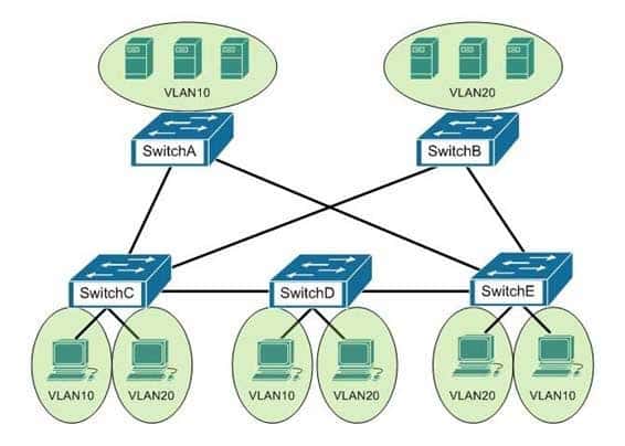
200-301 Part 05 Q16 058 You would like to designate the root bridges for VLANS 10 and 20. Which switches should you designate as the root bridges?
- Switch A for VLAN 10 and Switch E for VLAN 20
- Switch A for VLAN 10 and Switch B for VLAN 20
- Switch A for VLAN 10 and Switch C for VLAN 20
- Switch D for VLAN 10 and Switch B for VLAN 20
- Switch E for VLAN 10 and Switch A for VLAN 20
- Switch B for VLAN 10 and Switch E for VLAN 20
Explanation:
You should designate Switch A for VLAN 10 and Switch B for VLAN 20. The STP root bridge for a particular VLAN should be placed as close as possible to the center of the VLAN. If the majority of network traffic is between the hosts and servers within each VLAN, and the servers are grouped into a server farm, then the switch that all hosts will be sending their data to is the ideal choice for the STP root. Cisco’s default implementation of STP is called Per-VLAN Spanning Tree (or PVST), which allows individual tuning of the spanning tree within each VLAN. Switch A can be configured as the root bridge for VLAN 10, and Switch B can be configured as the root bridge for VLAN 20, resulting in optimized traffic flow for both. None of the other switches is in the traffic flow of all data headed towards the VLAN 20 or VLAN 10 server farms, so they would not be good choices for the root bridge for either VLAN. Care should be taken when adding any switch to the network. The addition of an older, slower switch could cause inefficient data paths if the old switch should become the root bridge.Objective:
LAN Switching Fundamentals
Sub-Objective:
Configure, verify, and troubleshoot STP protocols -
Which of the following statements are true with regard to the network shown in the exhibit? (Click the Exhibit(s) button.)
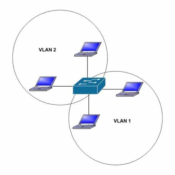
200-301 Part 05 Q17 059 - there is one broadcast domain and one collision domain
- there is one broadcast domain and four collision domains
- there are two broadcast domains and two collision domains
- there are two broadcast domains and four collision domains
- the hosts in VLAN1 could use IP addresses 192.168.5.4/24 and 192.168.5.5/24 and the hosts in VLAN2 could use IP addresses 192.168.6.1/24 and 192.168.6.2/24
- the hosts in VLAN2 could use IP addresses 192.168.5.5/24 and 192.168.6.5/24
Explanation:
There are two broadcast domains and four collision domains in the network shown in exhibit. A Virtual LAN (VLAN) is a group of networking devices in the same broadcast domain. A broadcast domain is a group of devices such that when one device in the group sends a broadcast, all the other devices in the group will receive that broadcast. Because there are two VLANs shown in the exhibit, VLAN1 and VLAN2, there are two broadcast domains. A switch will not forward broadcast frames between VLANs. A collision domain is a domain where two or more devices in the domain could cause a collision by sending frames at the same time. Each switch port is a separate collision domain. Because there are four switch ports in the exhibit, there are four collision domains.The hosts in VLAN1 could use IP addresses 192.168.5.4/24 and 192.168.5.5/24 and the hosts in VLAN2 could use IP addresses 192.168.6.1/24 and 192.168.6.2/24. Hosts in different VLANs must have IP addresses that are in different subnets.
The other options that offer IP address plans are incorrect because they either place hosts from different VLANs in the same subnet, or place hosts in the same VLAN in different subnets.
Objective:
LAN Switching Fundamentals
Sub-Objective:
Configure, verify, and troubleshoot VLANs (normal/extended range) spanning multiple switches -
Which command was used to create the following configuration?
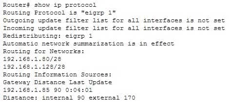
200-301 Part 05 Q18 060 -
Router(config-router)# network 192.168.1.0 0.0.0.15
-
Router(config-router)# network 192.168.1.0 255.255.255.0
-
Router(config-router)# network 192.168.1.80

Router(config-router)# network 192.168.1.128
-
Router(config-router)# network 192.168.1.0
Explanation:
The network 192.168.1.0 command instructs the router to activate EIGRP on every interface that belongs to the class C network 192.168.1.0. The exhibit indicates that the router is running EIGRP on two subnets of 192.168.1.0 (192.168.1.80/28 and 192.168.1.128/28). Since both of these are subnets of the same class C network number, only the class C address needs to be referenced with a network statement. All interfaces that will participate in EIGRP must be specified with a network command that specifying the network of which the interface is a member. Failure to do so will result in neighbor relationships not forming. In the example below, Router A and Router B are directly connected, but not forming a neighbor relationship. The network they share is the 192.168.5.0/24 network. The output of the show run command for both routers reveals that Router B does not have EIGRP running on the 192.168.5.0 network.

200-301 Part 05 Q18 061 The network 192.168.1.0 0.0.0.15 command is incorrect because only the class C network number (192.168.1.0) needs to be referenced to enable EIGRP on all subnets. It is actually valid to include an inverse mask with EIGRP network statements, but it is unnecessary in this case, and the network/mask provided does not match either of the routed networks.
The network 192.168.1.0 255.255.255.0 command is incorrect because the mask is unnecessary in this case, and if masks are included, they must be expressed inversely (0.0.0.255).
It is unnecessary to configure two network commands in this example, as both networks are subnets of the same class C network (192.168.1.0), and a single network command can enable EIGRP on both. Additionally, if specific subnets are referenced in network commands, it is necessary to include an inverse mask after them, or EIGRP will automatically summarize the command to the classful boundary.
Objective:
Routing Fundamentals
Sub-Objective:
Configure, verify, and troubleshoot EIGRP for IPv4 (excluding authentication, filtering, manual summarization, redistribution, stub) -
-
Which of the following represents the correct method of assigning an IP address and default gateway to a switch?
-
Switch(config)# interface vlan1

Switch(config-if)# ip address 10.0.0.1 255.0.0.0

Switch(config-if)# default-gateway 10.0.0.254
-
Switch(config)# ip default-gateway 10.0.0.254 Switch(config)# interface vlan1 Switch(config-if)# ip address 10.0.0.1 255.0.0.0 -
Switch(config)# ip address 10.0.0.1 255.0.0.0

Switch(config)# default-gateway 10.0.0.254
-
Switch(config)# ip address 10.0.0.1 255.0.0.0

Switch(config)# interface vlan1

Switch(config)# ip default-gateway 10.0.0.254
Explanation:
IP addresses are assigned to switches by assigning the address to VLAN 1 using the ip address command, while the default gateway is configured in global configuration mode using the ip default-gateway command. A default gateway is assigned to a Layer 2 switch using the following command syntax, where h.h.h.h is the IP address of the default gateway:Switch(config)# ip default-gateway h.h.h.h
An IP address is assigned to a Layer 2 switch using the following command syntax, where h.h.h.h is the IP address and m.m.m.m is the subnet mask:
Switch(config)# interface vlan1
Switch(config-if)# ip address h.h.h.h m.m.m.m
Configuring an IP address on a switch is usually accompanied by adding a default gateway as well. Switches do not require an IP address to perform their function on the network. IP addresses are added so that an administrator can make a Telnet connection to the switch to manage the switch. If this Telnet access does not occur on the same local subnet with the switch, which is unlikely, or if the administrator is trying to Telnet to the switch using a host that resides a VLAN other VLAN1 (the management VLAN) the absence of a gateway address will render the switch incapable of answering Telnet connection attempts. Therefore, a gateway address is usually required on the switch to make a telnet connection.
The following command set is incorrect because the command setting the default gateway must be executed in global configuration mode, not in configuration mode, for VLAN1:
Switch(config)# interface vlan1
Switch(config-if)# ip address 10.0.0.1 255.0.0.0
Switch(config-if)# default-gateway 10.0.0.254
The following command set is incorrect because the IP address must be configured in configuration mode for VLAN1, not global configuration mode:
Switch(config)# ip address 10.0.0.1 255.0.0.0
Switch(config)# default-gateway 10.0.0.254
The following command set is incorrect because an IP address must be configured in configuration mode for VLAN1. Also, if you executed the command interface vlan1, the prompt would change to Switch(config-if)#. Once it did, that would be an incorrect mode for entering the default gateway.
Switch(config)# ip address 10.0.0.1 255.0.0.0
Switch(config)# interface vlan1
Switch(config)# ip default-gateway 10.0.0.254
Objective:
Infrastructure Management
Sub-Objective:
Configure and verify device management -
-
Which statement best describes a converged network?
- a network with real-time applications
- a network with a mix of voice, video, and data traffic
- a network with a mix of voice and video traffic
- a network with mix of data and video traffic
Explanation:
A converged network is a combination of voice, video, and data traffic. Network convergence is a migration from maintaining multiple service-specific networks, namely data voice and video, to a single IP-based network. All services are delivered on the same network, reducing infrastructure costs. Despite the benefits that network convergence provides, it is highly susceptible to network delays, especially for real-time traffic. Converged networks frequently face the following problems:
– Bandwidth: As all the voice and video networks are combined into one universal converged network, bandwidth capacity becomes a priority.
– Packet loss: When links become congested, packets will be dropped. Voice and video traffic are intolerant of dropped packets.
-Delay: Delay represents the time it takes for packets to traverse the network and reach their destinations. While some delay is expected, delay increases when links are over-subscribed.Voice and video traffic are intolerant of high or variable delay. A packet that arrives late is no better than a packet that does not arrive. Delays can be variable and fixed.
Fixed delays are constant and mostly induced by the computing software of the hardware devices, such as processing delay and packetization delay.
Variable delays, known as jitter, cause problems for voice and video.
Objective:
Network Fundamentals
Sub-Objective:
Compare and contrast network topologies