200-301 : Cisco Certified Network Associate (CCNA) : Part 08
-
Examine the network diagram.
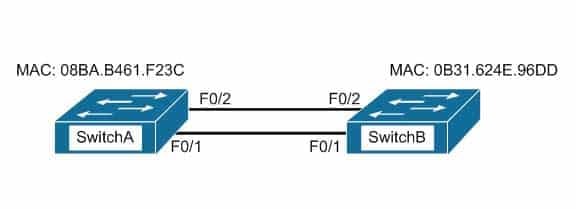
200-301 Part 08 Q01 073 Which switch port(s) will be in a forwarding state? (Choose two.)
- SwitchA – Fa0/1 and Fa0/2
- SwitchA – Fa0/1
- SwitchA – Fa0/2
- SwitchB – Fa0/1
- SwitchB – Fa0/2
Explanation:
Both switch ports on Switch A and Fa0/1 on Switch B will be in a forwarding state. Switch A will become the STP root bridge due to its lower MAC address. All ports on the root bridge will become designated ports in a forwarding state. Switch B has redundant connectivity to the root bridge, and must block one of its interfaces to prevent a switching loop. Both interfaces are the same speed (FastEthernet), and thus their cost to the root is the same. Finally, the interface with the lowest number will become the forwarding port. F0/1 has a lower port number than F0/2, so F0/1 becomes a forwarding port, and F0/2 becomes a blocking port.In this scenario there are only two switches in the diagram. However, if there were more switches and Switch A were not the root bridge, the result would be the same with regard to the ports between Swicth A and B. Whenever there are redundant links between switches, one of the four ports involved will be set to a blocking (or in the case of RSTP, discarding) mode. The logic will still be the same, since the cost to get to the root bridge will still be equal if the port speeds are equal.
Without STP (which can be disabled) operating on switches with redundant links, such as those in the figure, loops can and almost surely will occur. For example, if a host connected to SwitchA were to send an ARP request for the MAC address of a host connected to SwitchB, the request could loop and cause a broadcast storm, slowing performance dramatically. This would probably occur when any host connected to either switch sends a broadcast frame, such as a DHCP request.
Rapid Spanning Tree Protocol (RSTP) uses the term discarding for a switch port that is not forwarding frames.
Objective:
LAN Switching Fundamentals
Sub-Objective:
Configure, verify, and troubleshoot STP protocols -
The diagram below shows the state of the switch interfaces after STP has converged.
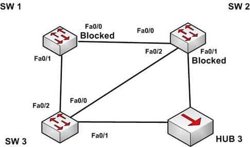
200-301 Part 08 Q02 074 Based on the interface states, which of the following statements are true? (Choose all that apply.)
- The Fa0/2 interface on SW 2 is a designated port
- SW 3 is the root bridge
- SW 2 is the root bridge
- The Fa0/0 interface on SW 2 is a designated port
- The Fa0/0 interface on SW 2 is a root port
Explanation:
Convergence has occurred in a spanning-tree network when all switch ports are in either a forwarding state or a blocking state (known as discarding state in RSTP). You can use the location of these blocked and forwarding ports to infer the location of the root bridge and the state of any unlabeled ports in the diagram.SW3 is the root bridge and the Fa0/0 interface on SW2 is a designated port. It can be determined that SW3 is the root bridge because all of its ports are in a forwarding state. Any switch that has at least one port blocking (such as SW1 and SW2) are non-root bridges. As there must be a root bridge, that leaves SW3 as the only candidate.
After establishing that SW3 is the root, it can be determined that the connection between SW1 and SW2 is a segment that does not have a direct connection to the root bridge. These sections must have one end set as a designated port and thus set to forward. Since the Fa0/0 interface on SW2 is forwarding, it is the designated port for that segment.
The Fa0/2 interface on SW2 is not a designated port. The interface on each non-root switch with the lowest cost path to the root bridge will be the root port. Since SW3 is the root bridge, the connection to SW3 via Fa0/2 is the lowest cost path to the root bridge for SW1 and thus is a root port, not a designated port. Moreover, designated ports only exist on segments that do not have a direct connection to the root bridge.
SW2 is not the root bridge. One of its ports is blocking, which will not occur on a root bridge.
The Fa0/0 interface on SW2 is a not root port. It is the designated port for the segment between SW1 and SW2.
The process of determining these port states occurs in this order:
1. Selection of the root bridge. When all bridge priorities have been left to their default, all switches will have same bridge priority. When that is the case, the switch with the lowest MAC address will be selected root bridge. ALL ports are in a forwarding state on the root bridge, which explains why all of the ports on SW3 will be in a forwarding state.
2. Determination of the root ports on each non-root bridge. Each non-root bridge will select the interface it possesses with the least cost path to the root bridge. Once selected, that port will be placed in a forwarding state.
3. Determination of the designated port on each segment that does not connect directly to the root bridge. There is one such segment in the diagram (SW1 to SW2). The interface on either end of the segment that has the least cost path to the root bridge will be the designated port for that section. It may have several paths, but the least cost path is used in the determination of the designated port for the segment.Once determined, the designated ports will be set to forwarding, and all ports that are neither root nor designated ports will be set to blocking.
Objective:
LAN Switching Fundamentals
Sub-Objective:
Configure, verify, and troubleshoot STP protocols -
When a router has been configured with a loopback address, which of the following determines the OSPF router ID?
- The highest MAC address assigned to a physical interface on the router
- The lowest priority of a physical interface on the router
- The lowest IP address assigned to a physical interface on the router
- The highest IP address assigned to a loopback interface on the router
Explanation:
Routers configured with OSPF must be assigned a router ID (RID), which is an IP address unique across the entire OSPF autonomous system. The RID can be assigned manually with the router-id command, or it will be determined automatically by OSPF. If the RID has not been manually assigned, then OSPF will use the highest numerical IP address of a loopback interface on the local router. If there are no configured loopback interfaces, then the RID will be determined by the highest numerical IP address on an active physical interface. The sequence for determining the RID is as follows:
1. Any address manually configured with the router-id command
2. The highest IP address on a loopback interface
3. The highest IP address on an active physical interfaceEither of the first two options would be a recommended best practice, since they each offer fault tolerance to the RID. If the RID is determined by a physical interface IP address, then the entire OSPF routing process is bound to an interface that could become unplugged or go down due to network reasons.
Loopback interfaces remain operational unless they are manually shut down. Loopback interfaces are configured as follows:
Router(config)# interface loopback0
Router(config-if)# ip address 192.168.1.254 255.255.255.255
The highest media access control (MAC) address assigned to a physical interface on the router is not used. IP addresses are used for the determination of the router ID.
Priorities are not used to determine the OSPF router ID. Priorities are used by OSPF to influence the election of the designated router (DR) and backup designated router (BDR) on a multi-access segment.
Router IDs are determined by the highest IP address on a loopback or physical interface, not the lowest.
Objective:
Routing Fundamentals
Sub-Objective:
Configure, verify, and troubleshoot single area and multi-area OSPFv2 for IPv4 (excluding authentication, filtering, manual summarization, redistribution, stub, virtual-link, and LSAs) -
Which layer in the Open Systems Interconnection (OSI) model defines an Internet Protocol (IP) address that helps in selecting the route to the destination?
- Data Link
- Network
- Application
- Transport
Explanation:
The Network layer in the OSI model defines a logical address that helps select the route to the destination. Logical addresses, such as IP addresses or IPX-SPX addresses, are used by routers to forward the packets to the destination. This is accomplished systematically by comparing the destination address with the network addresses listed in the routing table. The logical layout of the network is also defined at this layer. The Network layer is primarily concerned with logical addressing, routing, and path determination.Protocol data units (PDUs) are called packets at the Network layer. The information that is applied at this layer, which consists of IP addresses, is used in the routing process.
The Data Link layer does not define an IP address. This layer ensures the reliable transmission of data across a network and defines the Media Access Control (MAC) address, which defines the physical device addressing. This layer also defines the format of the header and trailer.
Protocol data units (PDUs) are called frames at the Data Link layer. The information that is applied at this layer, which consists of MAC addresses, is used in the switching process.
The application layer does not define an IP address. The application layer is responsible for interacting directly with the application and provides application services, such as e-mail, FTP, and Telnet. It also defines the user authentication process.
The Transport layer does not define an IP address. The Transport layer is responsible for the error-free and sequential delivery of data. This layer is used to manage data transmission between devices, a process known as flow control.
Protocol data units (PDUs) are called segments at the Transport layer, where the two protocols TCP and UDP operate. Windowing, which is the real-time management of the number of packets that can be received without an acknowledgement, is handled by TCP at this layer.
Objective:
Network Fundamentals
Sub-Objective:
Compare and contrast OSI and TCP/IP models -
Refer to the partial output of the show interfaces command:
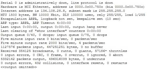
200-301 Part 08 Q05 075 What does the Serial 0 is administratively down, line protocol is down line indicate with certainty?
- There is no problem with the physical connectivity.
- There is a configuration problem in the local or remote router.
- There is a problem at the telephone company’s end.
- The shutdown interface command is present in the router configuration.
Explanation:
The Serial 0 is administratively down, line protocol is down line in the output of the show interfaces command indicates the following:
– The shutdown interface command is present in the router configuration. This indicates that the administrator might have manually shut down the interface by issuing the shutdown command.
– A duplicate Internet Protocol (IP) address might be in use.This line does not show that there is no problem with the physical connectivity. Since the interface is administratively shut down, there is no way of determining the operational status of the physical layer.
The Serial 0 is administratively down, line protocol is down line does not indicate a configuration problem in the local or remote router. A problem in the configuration of local or remote router would be indicated by the Serial 0 is up, line protocol is down message.
This line does not show that there is a problem at the telephone company’s end. Since the interface is administratively shut down, there is no way of determining the operational status of the physical layer or protocol layer on the other end of the line.
Objective:
Infrastructure Management
Sub-Objective:
Use Cisco IOS tools to troubleshoot and resolve problems -
The following exhibit displays the MAC address table of a switch in your network, along with the location of each device connected to the switch:
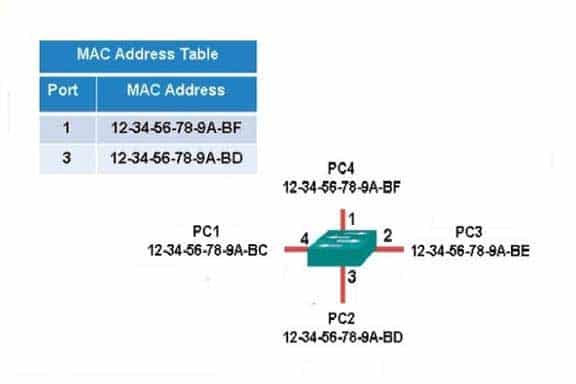
200-301 Part 08 Q06 076 Which of the following frames will be flooded to all ports after it is received by the switch?
- source MAC: 12-34-56-78-9A-BD, destination MAC: 12-34-56-78-9A-BF
- source MAC: 12-34-56-78-9A-BF, destination MAC: 12-34-56-78-9A-BD
- source MAC: 12-34-56-78-9A-BF, destination MAC: 12-34-56-78-9A-BC
- source MAC: 12-34-56-78-9A-BC, destination MAC: 12-34-56-78-9A-BF
Explanation:
The frame with a source MAC of 12-34-56-78-9A-BF and a destination MAC of 12-34-56-78-9A-BC would be sent to all ports because the destination MAC address is not already in the MAC address table.The frame with a source MAC of 12-34-56-78-9A-BD and a destination MAC of 12-34-56-78-9A-BF would not be sent to all ports because the destination MAC address is in the MAC address table.
The frame with a source MAC of 12-34-56-78-9A-BF and a destination MAC of 12-34-56-78-9A-BD would not be sent to all ports because the destination MAC address is in the MAC address table.
The frame with a source MAC of 12-34-56-78-9A-BC and a destination MAC of 12-34-56-78-9A-BF would not be sent to all ports because the destination MAC address is in the MAC address table.
Objective:
LAN Switching Fundamentals
Sub-Objective:
Interpret Ethernet frame format -
Which trunk encapsulation defines one VLAN on each trunk as a native VLAN?
- ISL
- IEEE 802.1q
- IEEE 802.11a
- auto
Explanation:
IEEE 802.1q defines one VLAN on each trunk as the native VLAN.The default value of a native VLAN is VLAN1. The IEEE 802.1q method does not encapsulate frames when forwarded over a trunk in a native VLAN; that is, IEEE 802.1q does not add its header information while transmitting frames in the native VLAN. This traffic is called untagged traffic. Frames originating from other VLANs, however, will have a 4-byte 802.1q header inserted into the frame to identify the VLAN number.
The native VLAN number can be changed if desired. If done it should be done on both ends of the connection. Otherwise, traffic that uses the native VLAN (untagged traffic) will not be able to cross the link. The commend to change the native VLAN is
Switch(config)#switchport trunk native vlan vlan number
Inter Switch Link (ISL) does not define one VLAN on each trunk as a native VLAN. ISL is the Cisco proprietary trunk encapsulation, and it can only be used between two Cisco switches.
IEEE 802.11a is a wireless standard defined by the IEEE, and has nothing to do with VLANs.
Auto is not an encapsulation method. The auto trunking mode is a method for negotiating an encapsulation method over trunk links.
Objective:
LAN Switching Fundamentals
Sub-Objective:
Configure and verify Layer 2 protocols -
Which command will display the Virtual LAN (VLAN) frame tagging method for a switch link?
- show vlan
- show vlan encapsulation
- show vtp status
- show interfaces trunk
Explanation:
The show interfaces trunk command displays the list of trunk ports and the configured VLAN frame tagging methods.Sample output of the show interfaces trunk command would be as follows:
SwitchB# show interfaces trunk
Port Mode Encapsulation Status Native vlan
Fa0/1 on 802.1q trunking 1
Fa0/2 on 802.1q trunking 1
Fa0/3 on 802.1q trunking 1
<<output omitted>>
The show vlan command displays the VLAN number, name, status, and ports assigned to individual VLANs. Although the command cannot be used to determine the frame tagging method used for each trunk, it can be used to determine which ports are trunk ports by the process of elimination.
In the output below, generated from a six-port switch, the missing port (Fa0/6) is a trunk port. For communication to be possible between the two VLANs configured on the switch, Fa0/6 must be connected to a router, and trunking must be configured on the router end as well. The command is also useful for verifying that a port has been assigned to the correct VLAN as it indicates in the VLAN column the VLAN to which each port belongs.
Switch# show vlan

Vlan name Status Ports
1 default active Fa0/1, Fa0/2, Fa0/3, Fa0/4
58 vlan 58 active Fa0/5
The show vlan encapsulation command is not a valid command for Cisco switches.
The show vtp status command does not display VLAN frame tagging method. The command is used to verify the status of VTP. The output of the show vtp status command would be as follows:
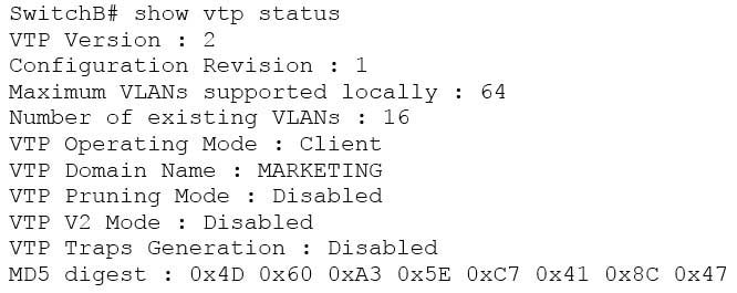
200-301 Part 08 Q08 077 Line 6 of the given output indicates that the switch is operating in VTP Client mode. There are three possible VTP modes in which a switch can operate: Server, Client, and Transparent.
– In Server mode, any changes made in the switch, such as adding a VLAN, will be recorded in the local database and also passed on to the other switches, where the change will be added.
– In Client mode, the switch will accept and record changes from switches in Server mode, but will not accept changes made on the local switch.
– In Transparent mode, the switch adds changes made locally to the database, but will not send or accept changes sent from other switches.The mode in use could be a useful piece of information during troubleshooting. For example, if you were unsuccessfully attempting to add a VLAN to the database, the reason would be that the switch is in VTP Client mode. If you were adding a VLAN in Transparent mode, the VLAN would be added to the local database but fail to appear on the other switches. If the switch were in Transparent mode, Line 6 in the above output would appear as follows:
VTP Operating Mode: Transparent
Only switches operating in VTP Server mode can accept changes to the VLAN database. This situation could be corrected easily and a VLAN 50 could be successfully added at two different configuration prompts by executing the following commands:
At global configuration mode:
switchB# config t
switchB(config)# vtp mode server
switchB(config)# vlan 50

At VLAN configuration mode:
switchB# vlan database
switchB(vlan)# vtp server
switchB(vlan)# vlan 50
Objective:
LAN Switching Fundamentals
Sub-Objective:
Configure, verify, and troubleshoot VLANs (normal/extended range) spanning multiple switches -
View the following network diagram:
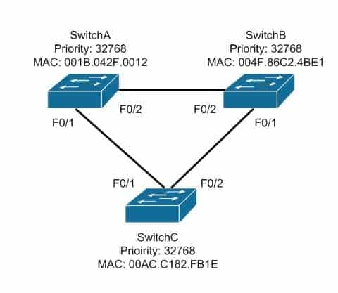
200-301 Part 08 Q09 078 Which switch will become the root bridge?
- SwitchA
- SwitchB
- SwitchC
- The root bridge cannot be determined from the given information.
Explanation:
SwitchA will become the root bridge. The bridge ID, also known as the switch ID, is used to elect the root bridge in a redundant network topology. The bridge ID has two components:
– Switch’s priority number: Configured as 32768 on Cisco switches by default
– Switch’s Media Access Control (MAC) address: The burnt-in hardware address of the network interface cardThe switch with the lowest bridge ID is selected as the root bridge. If the same priority number is configured on two or more switches in the network, the switch with the lowest MAC address will become the root. Bridge Protocol Data Units (BPDUs) communicate the details of the switch with the lowest bridge ID in the network. The election process for the root bridge takes place every time there is a topology change in the network. A topology change may occur due to the failure of a root bridge or the addition of a new switch in the network. The root bridge originates BPDUs every two seconds, which are propagated by other switches throughout the network. BPDUs are used as keepalives between switches, and if a switch stops receiving BPDUs from a neighboring switch for ten intervals (20 seconds), it will assume a designated role for the network segment.
Neither SwitchB nor SwitchC will become the root bridge. Although both have an equal priority value to SwitchA (32768), the MAC addresses of SwitchB and SwitchC are higher than that of SwitchA.
The root bridge can be determined with the information given. If the diagram did not indicate MAC addresses, then the root bridge would not be able to be determined, since the priorities are equal.
Objective:
LAN Switching Fundamentals
Sub-Objective:
Configure, verify, and troubleshoot STP protocols -
Which protocol is used in redundant network topologies to avoid receiving multiple copies of the same frame?
- 802.1q
- Spanning Tree Protocol
- Cisco Discovery Protocol
- Routing Information Protocol
Explanation:
Spanning Tree Protocol (STP) is used to remove switching loops in redundantly configured switched environments, and to create a single active Layer 2 path between any two network segments. This eliminates the chance of multiple copies of the same unicast frame being sent in the LAN. It also prevents broadcast packets from creating a broadcast storm when redundant connections exist between the switches. The benefits of STP include:
– Prevention of broadcast storms
– Prevention of multiple frame copies
– Media Access Control (MAC) address database stabilityWhenever a network segment can be handled by more than one switch, STP will elect one switch to take responsibility, and the other switches will be placed into a blocking state for the ports connected to that segment. In this way, only one switch receives and forwards data for this segment, which removes the potential for multiple copies of the same frame being generated. For STP to provide this functionality it must be running on all of the switches. Therefore, a properly implemented redundant topology STP is required in order to prevent multiple copies of the same unicast frame from being transmitted.
802.1q is a frame tagging method for identifying Virtual LAN (VLAN) memberships over trunk links. Frame tagging ensures identification of individual VLAN frames over a trunk link carrying frames for multiple VLANs. This frame tagging method is a standardized protocol that was developed by The Institute of Electrical and Electronics Engineers (IEEE). Cisco has also developed a proprietary frame tagging method known as Inter-Switch Link (ISL). 802.1q does not mitigate loops or the reception of multiple copies of frames. The IEEE specification for STP is 802.1d.
Cisco Discovery Protocol is a Cisco proprietary protocol used to collect hardware and protocol information for directly connected Cisco devices. CDP has nothing to do with redundant network topologies.
Routing Information Protocol (RIP) is a distance vector routing protocol. It populates routing tables dynamically about the topology changes. However, RIP does not control the receipt of multiple copies of frames in redundant network topologies.
Objective:
LAN Switching Fundamentals
Sub-Objective:
Configure, verify, and troubleshoot STP protocols -
Which of the following statements are true of Class C IP addresses?
- The decimal values of the first octet can range from 192 to 223
- The decimal values of the first octet can range from 1 to 126
- The first octet represents the entire network portion of the address
- The first three octets represent the entire network portion of the address
- The value of the first binary place in the first octet must be 0
- The value of the first two binary places in the first octet must be 11
Explanation:
A class C IP addresses will have the following characteristics:
– The decimal values of the first octet can range from 192 to 223
– The first three octets represent the entire network portion of the address
– The value of the first two binary place in the first octet must be 11Class B IP addresses will have the following characteristics:
– The decimal values of the first octet can range from 128 to 191
– The first two octets represent the entire network portion of the address
– The value of the first two binary place in the first octet must be 10Class A IP addresses will have the following characteristics:
– The decimal values of the first octet can range from 1 to 126
– The first octet represents the entire network portion of the address
– The value of the first binary place in the first octet must be 0Objective:
Network Fundamentals
Sub-Objective:
Compare and contrast IPv4 address types -
Which Cisco Internetwork Operating System (IOS) command would be used to define a static route for network 192.168.11.0 through default gateway 192.168.43.1?
-
router(config)# ip route 192.168.11.0 255.255.255.0 192.168.43.1 -
router# ip route 192.168.11.0 255.255.255.0 192.168.43.1
-
router(config)# ip classless 192.168.43.1
-
router(config)# ip default gateway 192.168.11.0 255.255.255.0 192.168.43.1
-
router# ip default gateway 192.168.43.1
Explanation:
The router(config)# ip route 192.168.11.0 255.255.255.0 192.168.43.1 command would be used to define a static route for network 192.168.11.0 through default gateway 192.168.43.1. Static routing is used to manually configure routes to remote networks. The syntax of the ip route command is as follows:ip route [destination_network] [mask] [next-hop_address or exit interface] [administrative_distance] [permanent]
The parameters of the command are as follows:
– destination_network: Defines the network that needs to be added in the routing table.
– mask: Defines the subnet mask used on the network.
– next-hop_address: Defines the default gateway or next hop router that receives and forwards the packets to the remote network.
– administrative_distance (AD): Static routes have an AD of 1, which can be changed to change the priority of the route.Static routing is often implemented in small yet stable networks where the number of routes is small and manageable, and the network can benefit from the elimination of the traffic that dynamic routing protocols would introduce. If this is the case, it is important that all routes be statically created, or else networking problems can occur. For example, if in the diagram below no route to the 192.168.110.128/26 network on Router 2 exists on Router 1, Host 1 will be unable to ping Host 2. The fact that Host 1 would still be able to ping the S0/0 interface on Router 2 could obscure this missing route.
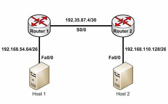
200-301 Part 08 Q12 079 Host 1 will be able to ping the S0/0 interface of Router 2 because the 192.35.87.4/30 network will be in the routing table of Router 1, being directly connected to Router 1. Directly connected routes are automatically placed in the routing table. However, if you executed the show run command on Router 1, the output would indicate that no route to the 192.168.110.128/26 exists:
<output omitted>
interface Fa0/1
ip address 192.168.54.65 255.255.255.192
no shutdown
interface S0/0
ip address 192.35.87.5 255.255.255.252
no shutdown
The option router# ip route 192.168.11.0 255.255.255.0 192.168.43.1 is incorrect because the ip route command should be configured in the global configuration mode.
The option router(config)# ip classless 192.168.43.1 is incorrect because the ip classless global configuration mode command allows a router to accept and forward packets for subnets that are not directly connected. The packets are forwarded to the best available supernet route.
The option router(config) # ip default gateway 192.168.11.0 255.255.255.0 192.168.43.1 is incorrect because the ip default gateway command is used to define the default gateway address when IP routing is disabled in the network.
Objective:
Routing Fundamentals
Sub-Objective:
Configure, verify, and troubleshoot IPv4 and IPv6 static routing -
-
DRAG DROP
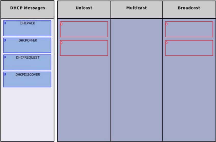
Group the special DHCP messages exchanged over the network, on the left, into the different transmission types, on the right.
200-301 Part 08 Q13 080 Question 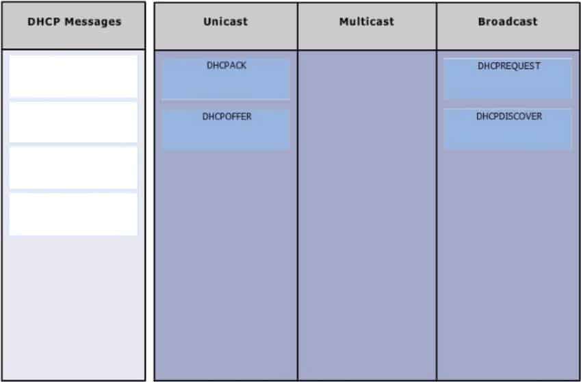
200-301 Part 08 Q13 080 Answer Explanation:
Dynamic Host Configuration Protocol (DHCP) is an enhancement over Bootstrap Protocol (BOOTP). DHCP is used to automate the distribution of IP address to clients from a central server. BOOTP protocol was also used distribute IP addresses, but was inflexible when changes were made in the network. DHCP offers the following three advantages, which also addressed the inflexibility of the BOOTP protocol:
– Automatic allocation of permanent IP addresses
– Automatic allocation of time bound (leased) IP addresses
– Provision of assigning static IP address or defining a pool of reserved IP addressThe following steps are used to allocate IP address dynamically using a Cisco IOS DHCP server:
1. The client device broadcasts a DHCPDISCOVER broadcast message to locate a Cisco IOS DHCP server.
2. The Cisco IOS DHCP server replies with a DHCPOFFER unicast message containing configuration parameters such as an IP address, a MAC address, a domain name, and a lease for the IP address for the client device.
3. The client sends back a DHCPREQUEST broadcast, which is a formal request for the offered IP address to the Cisco IOS DHCP server.
4. The Cisco IOS DHCP server replies to client device with DHCPACK unicast message acknowledging the allocation of the IP address to this client device.While DHCP is very useful in reducing the administrative burden of issuing IP configurations in a large network, Cisco best practices call for using static IP addressing in a small (6 or fewer hosts) network.
Objective:
Infrastructure Services
Sub-Objective:
Configure and verify DHCP on a router (excluding static reservations) -
Which command will save a dynamically learned MAC address in the running-configuration of a Cisco switch?
- switchport port-security mac-address
- switchport port-security
- switchport port-security sticky mac-address
- switchport port-security mac-address sticky
- switchport mac-address sticky
Explanation:
Issuing the switchport port-security mac-address sticky command will allow a switch to save a dynamically learned MAC address in the running-configuration of the switch, which prevents the administrator from having to document or configure specific MAC addresses. Once the approved MAC addresses have all been learned, the network administrator simply saves the running-configuration file to NVRAM with the copy running-config startup-config command.Switches dynamically build MAC address tables in RAM, which allow the switch to forward incoming frames to the correct target port. By default, an unlimited number of MAC addresses can be learned on a single switch port, whether it is configured as an access port or a trunk port. Switch ports can be secured by defining one or more specific MAC addresses that should be allowed to connect, and by defining violation policies (such as disabling the port) if additional hosts try to gain a connection. The following command secures a switch by manually defining an allowed MAC address:
switch(config-if)# switchport port-security mac-address 00C0.35F0.8301
This command statically defines the MAC address of 00c0.35F0.8301 as an allowed host on the switch port. Manually configuring all of your switch ports in this way, however, would require documenting all of your existing MAC addresses and configuring them specifically per switch port, which could be an extremely time-consuming task.
An example of the use of the switchport port-security mac-address sticky command is shown below:
Switch(config)#interface fastethernet0/16
Switch(config-if)#switchport port-security
Switch(config-if)#switchport port-security mac-address sticky
Switch(config-if)#switchport port-security maximum 1
With the above configuration, if a computer with a MAC address of 0000.00bb.bbbb were plugged into the switch, the following two things would occur:
– Only the host with MAC address 000.00bb.bbbb will be allowed to transmit on the port. This is a result of the port-security mac-address-sticky command, which instructs the switch to learn the next MAC address it sees on the port, and of the port-security maximum 1 command, which further instructs the switch that the address learned is the only address allowed on the port.
– All frames arriving at the switch with a destination address of 0000.00bb.bbb will be forwarded out on Fa0/16.The switchport port-security mac-address sticky command can also be used in combination with the interface-range command to make every port on the switch behave in this fashion as shown below for a 24-port switch.
Switch(config)#interface range fastethernet0/1-24
Switch(config-if)#switchport port-security
Switch(config-if)#switchport port-security mac-address sticky
Switch(config-if)#switchport port-security maximum 1
The switchport port-security mac-address command is incorrect since this command requires an additional argument to be valid (either a statically configured MAC address or the sticky option).
The switchport port-security command activates port security on the switch port, but does not configure sticky MAC address learning.
The switchport port-security sticky mac-address and switchport mac-address sticky options are incorrect because these are not valid Cisco IOS commands.
Objective:
Infrastructure Security
Sub-Objective:
Configure, verify, and troubleshoot port security -
Which of the following items are NOT required to match for two routers to form an OSPF adjacency?
- Area IDs
- Hello/Dead timers
- Passwords (if OSPF authentication has been configured)
- Process IDs
Explanation:
All of the listed items must match except for the process IDs. The process IDs are locally significant, which keeps multiple instances of OSPF separate on a router, and do not need to match between neighboring routers for the adjacency to form. Process identifiers can be valued from 1 to 65535.Adjacencies must be formed before routing updates can be exchanged. OSPF routers will form neighbor adjacencies on common subnets if the following three items match:
– Area IDs
– Hello/Dead timers
– Passwords (if OSPF authentication has been configured)Once an adjacency has been formed it will be maintained by the exchange of Hello messages. On a broadcast medium like Ethernet, they will be sent every 10 seconds. On point-to-point links, they will be sent every 30 seconds.
The show ip ospf interface interface number command can be used to display the state of the DR/BDR election process.
Consider the following output:
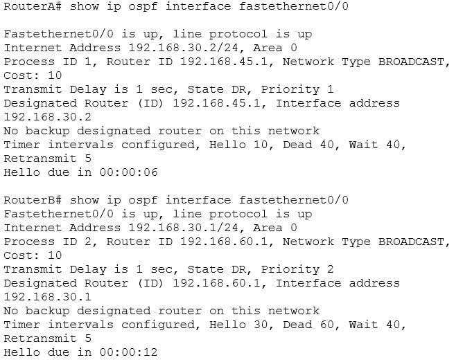
200-301 Part 08 Q15 081 The timer intervals’ configured output reveals that RouterA is showing a Hello timer of 10 seconds and a Dead timer of 40 seconds. RouterB has a Hello timer of 30 seconds and a Dead timer of 60 seconds. Hello/Dead timers have to match before OSPF routers will form an adjacency. If you executed the debug ip ospf events command on one of the routers, the router at serial /01 will not form a neighbor relationship because of mismatched hello parameters:
RouterA# debug ip ospf events
OSPF events debugging is on
RouterA#
*Nov 9 05:41:21.456:OSPF:Rcv hello from 10.16.2.3 area 0 from Serial0/1
192.168.35.1
*Nov 9 05:41:21.698:OSPF:Mismatched hello parameters from
192.168.35.1
Hellos are used to establish neighbor adjacencies with other routers. On a point-to-point network, hello packets are sent to the multicast address 224.0.0.5, which is also known as the ALLSPFRouters address.
Area IDs have to match for OSPF routers to form an adjacency. Both of these routers have the interface correctly configured in matching Area 0.
The interface priorities do not have to match for OSPF routers to form an adjacency. Interface priorities can be configured to control which OSPF router becomes the designated router (DR) or backup designated router (BDR) on a multi-access network segment.
Objective:
Routing Fundamentals
Sub-Objective:
Configure, verify, and troubleshoot single area and multi-area OSPFv2 for IPv4 (excluding authentication, filtering, manual summarization, redistribution, stub, virtual-link, and LSAs) -
Which two are the limitations of the service password-encryption command? (Choose two.)
- It uses the MD5 algorithm for password hashing.
- It uses the Vigenere cipher algorithm.
- An observer cannot read the password when looking at the administrator’s screen.
- The algorithm used by this command cannot protect the configuration files against detailed analysis by attackers.
Explanation:
The following are limitations of the service password-encryption command:
– It uses the Vigenere cipher algorithm, which is simple in nature.
– A cryptographer can easily crack the algorithm in a few hours.
– The algorithm used by this command cannot protect the configuration files against detailed analysis by attackers.The service password-encryption command does not use the MD5 algorithm for password hashing. The MD5 algorithm is used by the enable secret command.
The option stating that an observer cannot read the password when looking at the administrator’s screen is incorrect because this is an advantage of the service password-encryption command.
Objective:
Infrastructure Security
Sub-Objective:
Configure, verify, and troubleshoot basic device hardening -
You have been assigned a network ID of 172.16.0.0/26. If you utilize the first network resulting from this ID, what would be the last legitimate host address in this subnet?
- 172.16.0.64
- 172.16.0.63
- 172.16.0.62
- 172.16.0.65
Explanation:
When a class B address such as 172.16.0.0 is subnetted with a /26 mask, the subnet mask in dotted decimal format is 255.255.255.192. This means that the interval between the network IDs of the resulting subnets is 64. The resulting network IDs are as follows:172.16.0.0
172.16.0.64
172.16.0.128
172.16.0.192
172.16.1.0
and so on.For the network ID 172.16.0.0, the last address in the range is 172.16.0.63, which is the broadcast address. Neither the network ID nor the broadcast address for any subnet can be assigned to computers. This means that the addresses that can actually be assigned range from 172.16.0.1 to 172.16.0.62. The last legitimate host address, therefore, is 172.16.0.62.
172.16.0.63 cannot be used because it is the broadcast address for the 172.16.0.0 network.
172.16.0.64 is the network ID for the 172.16.0.64 network, and 172.16.0.65 is the first address in the second network.
Objective:
Network Fundamentals
Sub-Objective:
Apply troubleshooting methodologies to resolve problems -
Which Cisco IOS command enables a router to copy IOS images to a router?
- copy tftp flash
- copy flash tftp
- copy running-config tftp
- copy running-config startup-config
- copy tftp running-config
Explanation:
The copy tftp flash command enables a router to copy an IOS image (the router operating system) to a router from a TFTP server. One router can act as a TFTP server to the other in this process.The following example illustrates the steps to copy an image from Router A to Router B:
– Verify the connectivity between Router A and Router B using the ping command.
– Check the image size on both of the routers with the show flash command to verify that enough space exists on Router B.
– Configure Router A as the TFTP server using the configure terminal command. Use the tftp-server flash [partition-number:]filename1 [alias filename2] [access-list-number] command to define the path to system image that needs to transferred. There can be multiple entries for multiple images.
– Copy the image from Router A to Router B using the copy tftp flash command.
– Verify the flash for the copied new image on Router B with the show flash command.The copy flash tftp command is used to copy an IOS image from the router to a TFTP server.
The copy running-config tftp command is used to copy the active or running configuration file from RAM to a TFTP server.
The copy running-config startup-config command copies the active or running configuration from RAM to NVRAM. This command creates the configuration file that will be used as the startup configuration at reboot. This should always be done after making changes to the router so that the changes are saved when the router is rebooted.
The copy tftp running-config command merges a backup configuration with the currently active running configuration in RAM.
Objective:
Infrastructure Management
Sub-Objective:
Perform device maintenance -
Which device in the given network diagram has as its primary responsibility the regulation of network traffic flow based on different trust levels for different computer networks?
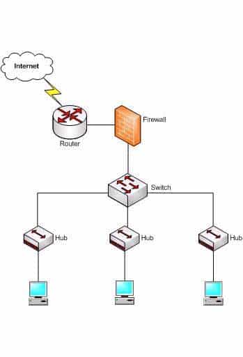
200-301 Part 08 Q19 082 - the router
- the switch
- the hub(s)
- the firewall
Explanation:
The firewall has as its primary responsibility the regulation of network traffic flow based on different trust levels for different computers or networks. In the network diagram shown in the exhibit, a firewall protects the network from unauthorized access attempts. A firewall can be implemented in hardware or software. Firewalls permit, deny, or filter data packets coming into and going out of the network. This helps prevent unauthorized access attempts from outside the network.The primary function of a router is to perform routing between two subnets or between dissimilar network technologies. Routers can provide limited firewall functionality, but a firewall is a dedicated hardware or software solution with the primary responsibility of securing the network. A router does not have as its primary responsibility the regulation of network traffic flow based on different trust levels.
Switches work at Layer 2 in the Open System Interconnection (OSI) model and perform the function of separating collision domains. A switch does not have as its primary responsibility the regulation of network traffic flow based on different trust levels.
A hub is a device that provides a common connection point for network devices. The primary responsibility of a hub is not to regulate network traffic flow based on different trust levels.
Objective:
Network Fundamentals
Sub-Objective:
Describe the impact of infrastructure components in an enterprise network -
The exhibit displays the MAC address table of a switch in your network, along with the location of each device connected to the switch.

200-301 Part 08 Q20 083 Which of the following frames will cause the switch to add a new MAC address to its table and forward the frame to all ports when the frame is received?
- source MAC: 12-34-56-78-9A-BC, destination MAC: ff-ff-ff-ff-ff-ff
- source MAC: ff-ff-ff-ff-ff, destination MAC: 12-34-56-78-9A-BC
- source MAC: 12-34-56-78-9A-BF, destination MAC: 12-34-56-78-9A-BC
- source MAC: 12-34-56-78-9A-BC, destination MAC: 12-34-56-78-9A-BF
Explanation:
The only frame that will be handled in the specified way is the one with a source MAC of 12-34-56-78-9A-BC and a destination MAC of ff-ff-ff-ff-ff-ff. Since the source address 12-34-56-78-9A-BC is not already in the MAC table, the switch will add it. It will forward the frame to all ports because the destination is the broadcast MAC address of ff-ff-ff-ff-ff-ff.A frame with a source MAC of ff-ff-ff-ff-ff-ff and a destination MAC of 12-34-56-78-9A-BC is an impossible combination. That would mean that the frame is coming from all devices, which is not possible.
The frame with a source MAC of 12-34-56-78-9A-BF and a destination MAC of 12-34-56-78-9A-BC would be sent to all ports because the destination MAC address is not in the MAC address table. However, the switch would not add a new MAC address to the table because the source address is already in the table.
The frame with a source MAC of 12-34-56-78-9A-BC and a destination MAC of 12-34-56-78-9A-BF would not be forwarded to all ports because the destination MAC address is in the table. The switch would add a new MAC address to the table because the source MAC address is not currently in the MAC address table.
Objective:
LAN Switching Fundamentals
Sub-Objective:
Interpret Ethernet frame format