200-301 : Cisco Certified Network Associate (CCNA) : Part 11
-
Which Cisco IOS command can be used to troubleshoot switch startup problems on a Cisco Catalyst 2950 switch?
- show test
- show diagnostic
- show post
- show switchstartup
Explanation:
The Cisco IOS command show post is used on the 2900/3500XL, 2950/2955, 3550, 2970, and 3750 series switches to view and troubleshoot issues related to the Power On Self-Test (POST) on the switch. This command will find the POST test that failed on startup. The show test command is incorrect because it is a CatOS command, not a Cisco IOS command. The Cisco 2950 uses a Cisco IOS operating system and not the Catalyst operating system. The show test command is used on a switch to view any hardware errors that occurred at startup. It also provides information on the errors returned from the diagnostic tests. The following parameters can be used with this command:
– mod: An optional parameter used to specify the module number.
– diaglevel: Used to view the diagnostic level.
– diagfail-action: Used to view information on the action taken by the supervisor engine after the failure of a diagnostics test. The following code is a sample output of this command for module 2:
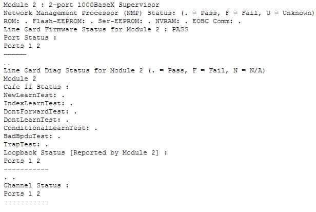
200-301 Part 11 Q01 100 The show diagnostic command is incorrect because this command is used on the Catalyst 6000 series, not the 2950. A variant of the command, show diagnostics, is used for the Catalyst 4000 series. These commands can be used on the relevant switches to view any hardware errors that occurred on startup. This command displays the Power-On Self-Test (POST) results.
The show switch startup command is not a valid Cisco IOS command.
Objective:
Infrastructure Management
Sub-Objective:
Use Cisco IOS tools to troubleshoot and resolve problems -
Why is it recommended to use Spanning Tree Protocol (STP) in Local Area Networks (LANs) with redundant paths?
- To prevent loops
- To manage VLANs
- To load balance across different paths
- To prevent forwarding of unnecessary broadcast traffic on trunk links
Explanation:
Spanning Tree Protocol (STP) is a Layer 2 protocol used in LANs to maintain a loop-free network topology by recognizing physical redundancy in the network and logically blocking one or more redundant ports. An example of switch redundancy is shown in the diagram below. The connection from SW4 to SW2, while providing beneficial redundancy, introduces the possibility of a switching loop.
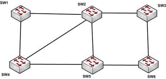
200-301 Part 11 Q02 101 STP probes the network at regular intervals to identify the failure or addition of a link, switch, or bridge. In the case of any topology changes, STP reconfigures switch ports to prevent loops. The end result is one active Layer 2 path through the switch network.
STP is not used for management of Virtual Local Area Networks (VLANs). VLAN Trunking Protocol (VTP) simplifies the management of VLANs by propagating configuration information throughout the switching fabric whenever changes are made. In the absence of VTP, switch VLAN information would have to be configured manually.
STP is not used to load-balance traffic across different redundant paths available in a topology. Load balancing allows a router to use multiple paths to a destination network. Routing protocols, Routing Information Protocol (RIP), RIPv2, Interior Gateway Routing Protocol (IGRP), Enhanced IGRP (EIGRP), and Open Shortest Path First (OSPF) support load balancing. Similarly, multiple links can be combined in a faster single link in switches. This can be achieved with the Fast EtherChannel or Gigabit EtherChannel features of Cisco switches.
STP does not prevent forwarding of unnecessary broadcast traffic on trunk links. This is achieved by manually configuring VLANs allowed on the trunk, or through VTP pruning.
Objective:
LAN Switching Fundamentals
Sub-Objective:
Configure, verify, and troubleshoot STP protocols -
Enhanced Interior Gateway Routing Protocol (EIGRP) uses which algorithm to select the best path to the destination?
- Diffusing Update Algorithm (DUAL)
- Dijkstra algorithm
- Bellman-Ford algorithm
- Shortest Path First (SPF) algorithm
Explanation:
EIGRP uses the Diffusing Update Algorithm (DUAL) to select the best path to the destination. EIGRP is a classless protocol that allows the use of variable length subnet masks (VLSM), and supports classless interdomain routing (CIDR) for the allocation of IP addresses. EIGRP is characterized by these components:
– DUAL: EIGRP implements DUAL to select paths free of routing loops. DUAL selects the best path and the second best path to the destination. The terminology used in DUAL is as follows:
– Successor: Best path selected by DUAL.
– Feasible successor: Second best path selected by DUAL. This is a backup route stored in the topology table.
– Feasible distance: The lowest calculated metric of a path to destination.
– Protocol-dependent modules: Different modules are used by EIGRP to independently support Internet Protocol (IP), Internetwork Packet Exchange (IPX), and AppleTalk routed protocols. These modules act as a logical interface between DUAL and routing protocols.
– Neighbor discovery and recovery: Neighbors are discovered and information about neighbors is maintained by EIGRP. A hello packet is multicast on 224.0.0.10 every five seconds and the router builds a table with the information. EIGRP also enables proper operation over a Non-Broadcast Multiple Access (NBMA) point-to-multipoint network. EIGRP multicasts a hello packet every 60 seconds on the multipoint Wide Area Network (WAN) interfaces (X.25, frame relay, or Asynchronous Transfer Mode).
– Reliable Transport Protocol (RTP): RTP is used by EIGRP to manage EIGRP packets. Reliable and ordered delivery of route updates is ensured using RTP.EIGRP updates about routes can contain five metrics: minimum bandwidth, delay, load, reliability, and maximum transmission unit (MTU). Of these five metrics, by default, only minimum bandwidth and delay are used to compute the best path.The Dijkstra algorithm and Shortest Path First (SPF) algorithm are used by the Open Shortest Path First (OSPF) routing protocol for selecting the best path to the destination, not by EIGRP.
The Bellman-Ford algorithm is used by Routing Information Protocol (RIP).
Objective:
Routing Fundamentals
Sub-Objective:
Compare and contrast interior and exterior routing protocols -
Examine the following output from SwitchD.
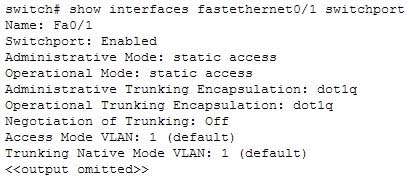
200-301 Part 11 Q04 102 Based on this output, what command MUST be executed for an 802.1q trunk to be created on port Fa0/1?
- switchport mode trunk
- switchport mode nonegotiate
- switchport trunk encapsulation 802.1q
- switchport trunk native VLAN
Explanation:
The command switchport mode trunk must be executed for a trunk to form. The output indicates that the Administrative Mode of the port is “static access,” which means the port has been configured as a static (fixed) access port. Access mode disables trunking on an access port. Below is a sample of the configuration required to allow a router to provide inter-VLAN routing between two VLANs residing on the switch:
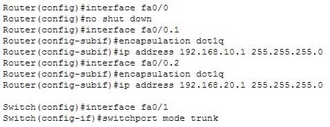
200-301 Part 11 Q04 103 For this example, the following statements are true:
– The trunk link connects to Fa0/0 on the router and Fa0/1 on the switch.
– The physical interface F0/0 on the router has been divided into two subinterfaces, Fa0/0.1 and Fa0/0.2.
– The encapsulation type of 802.1q has been specified on the two subinterfaces of the router.
– The physical interface on the switch has been specified as a trunk link.
– The IP addresses 192.168.10.1 and 192.168.20.1 should be the default gateways of the computers located in VLANs 1 and 2, respectively.The switchport mode nonegotiate command does not need to be executed because the switch is already configured for non-negotiation, as indicated by the output Negotiation of Trunking: Off. Trunk negotiation using the Dynamic Trunking Protocol (DTP) does not need to be enabled for a trunk to form.
The switchport trunk encapsulation 802.1q command does not need to be executed for a trunk to form. Also, the output Operational Trunking Encapsulation: dot1q indicates that 802.1q encapsulation is already configured.
The switchport trunk native VLAN command does not need to be executed. This command is used to change the native VLAN from its default of 1, but leaving it set to the default of 1 will not prevent the trunk from forming.
Objective:
Routing Fundamentals
Sub-Objective:
Configure, verify, and troubleshoot inter-VLAN routing -
As you are training a new junior technician, the trainee is examining the routing table. He tells you that there are four different routes to the same network in different routing databases. He asks you which of the routes will be used to populate the routing table.
What will your answer be, assuming that all routing protocols are set at the default administrative distance?
- The route with an R next to it
- The route with an S next to it
- The route with a C next to it
- The route with an I next to it
Explanation:
The route with a C next to it is a directly connected route and has an administrative distance of 0, which means it will be preferred over any routes with a larger value for administrative distance. Each routing protocol has a default administrative distance assigned. Administrative distance is used by the router to determine the preferred route when a route is learned from different routing protocols. This process can be manipulated by the administrator by using the distance command to alter the default assignments. It is significant to note that routers with no static routes and no routing protocols enabled will populate all directly connected routes to the routing table with no action on the part of the administrator. Routes that are NOT directly connected will not be in the routing table unless one of two things occurs:
– A static route is created by the administrator
– A routing protocol is enabled that allows the router to learn about the network and its route from another router running the same routing protocol For example, in the diagram below, R3 will have routes to the 192.168.3.0/24 ,192.168.1.0/24 and the 192.168.0.0/24 networks in its routing table by default. It will only have routes to the 192.168.2.0/24, 192.168.5.0/24, and 192.168.6.0/24 networks if a routing protocol is used or if an administrator creates static routes for each network.
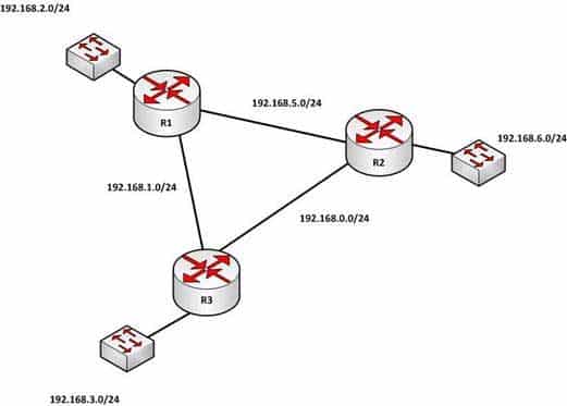
200-301 Part 11 Q05 104 When a packet is received by a router interface, the router de-encapsulates the frame or removes the layer two information (MAC data for Ethernet or DLCIs for frame relay) and then performs a lookup for the network ID of the network in which the destination IP address resides. When multiple routes exist, it will choose the one with the lowest administrative distance. The router only places the route with the lowest distance in the table.
The route with an R next to it is a route learned from Routing Information Protocol (RIP). It has a default administrative distance of 120, so it will not prefer over a directly connected route.
The route with an S next to it is a static route or one configured manually. It has an administrative distance of 1, so it will not be preferred over a directly connected route.
The route with an I next to it is a route learned from Internal Gateway Routing Protocol (IGRP). It has an administrative distance of 100, so it will not be preferred over a directly connected route.
Objective:
Routing Fundamentals
Sub-Objective:
Interpret the components of routing table -
What command can be used on a Cisco switch to display the virtual MAC address for the HSRP groups of which the switch is a member?
-
switch# show standby mac
-
switch# show hsrp mac
-
switch# show standby -
switch# show standby brief
Explanation:
The command show standby can be used to display the virtual MAC address for HSRP groups of which a switch is a member. This command displays information about HSRP on all configured interfaces and for all HSRP groups. It also displays hello timer information and the expiration timer for the standby switch. The standby switch will take over as the active switch if the timer expires before it hears a heartbeat from the active switch. Below is an example of the show standby command for the HSRP group 1:
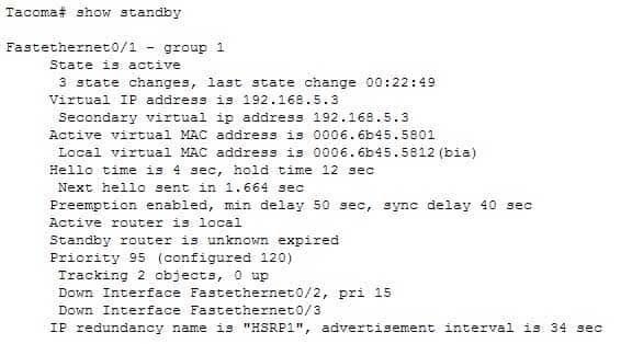
200-301 Part 11 Q06 105 In the above output, the following can be determined:
– The router is currently active for the group, as can be seen in line 2. The Active Virtual MAC address is 0006.6b45.5801, which includes the group number (1) in the last two positions, which is why the address is different from the routers actual MAC address shown on the next line. Special Note: Some router models (Cisco 2500, 4000 and 4500) WILL NOT use this altered MAC address format, but will instead use the real MAC address for the virtual MAC address and will display that MAC address as the virtual MAC address in the output of the show standby command. An example of the output of the show standby command on an older router such as the 2500 would be as follows:
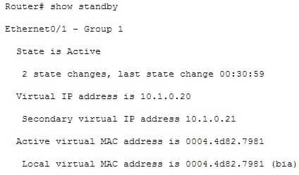
200-301 Part 11 Q06 106 These routers have Ethernet hardware that only recognize a single MAC address. In either case, if for some reason this router becomes the standby router, such as due to loss of interfaces, then when the interfaces come back up it will be able to recover the active role because it is set for preemption, as shown on line 10.
– The router is tracking two of its own interfaces. Because both interfaces are down, the router’s priority has been reduced by 25 (15 for Fastethernet0/2 and 10 for Fastethernet0/3), from the configured value of 120 to 95. This data is shown on lines 13-16. The default is 10 if not otherwise specified, as is the case for Fastethernet0/3.
– If either of the two interfaces comes back up, the priority will be increased by the amount assigned to the interface. For example, if Fastethernet0/3 comes back up, the priority will become 105 (95 + 10).
– The standby router is unreachable, which can be determined because it is marked unknown expired in line 12. This could be due to either a physical layer issue or an HSRP misconfiguration.The command show standby brief can be used to view summary information about HSRP groups of which the switch is a member. This information includes the group number, priority, state, active device address, standby address, and group address. It does not include the virtual MAC address.
The commands show standby mac and show hsrp mac are invalid due to incorrect syntax.
Objective:
Infrastructure Services
Sub-Objective:
Configure, verify, and troubleshoot basic HSRP -
-
Examine the diagram below:
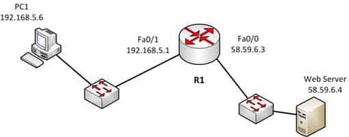
200-301 Part 11 Q07 107 You attempt to make a Telnet connection from PC1 to the switch connected to the Web server, but the connection fails. After making a console connection to the switch connected to the Web server and executing the show run command, you see the following information:
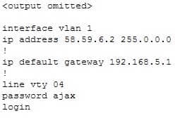
200-301 Part 11 Q07 108 Which value is NOT correct?
- the default gateway
- the VLAN number
- the password
- the login command
Explanation:
The switch is connected to the F0/0/ interface on the router R1. The address of Fa0/0 should be the default gateway for the switch. This means it should be 58.59.6.4 rather than 192.168.5.1.The VLAN number is correct. The IP address of a switch is set on the VLAN 1 interface of the switch. The password can be anything you desire, so that is correct.The login command is correct. This command instructs the switch to prompt for a password. Since there is a password configured, this will not prevent a connection to the switch.
Objective:
Infrastructure Management
Sub-Objective:
Configure and verify device management -
You have been asked to troubleshoot the NTP configuration of a router named R70. After executing the show run command, you receive the following partial output of the command that shows the configuration relevant to NTP:
clock timezone PST -8
clock summer-time PDT recurring
ntp update-calendar
ntp server 192.168.13.57
ntp server 192.168.11.58
interface Ethernet 0/0
ntp broadcast
Based on this output, which of the following statements is true?
- the time zone is set to 8 hours less than Pacific Standard time
- the router will listen for NTP broadcasts on interface E0/0
- the router will send NTP broadcasts on interface E0/0
- the router will periodically update its software clock
Explanation:
The router will send NTP broadcast on its E0/0 interface. The command ntp broadcast, when executed under an interface, instructs the router to send NTP broadcast packets on the interface. Any devices on the network that are set with the ntp broadcast client command on any interface will be listening for these NTP broadcasts. While the clients will not respond in any way, they will use the information in the NTP broadcast packets to synchronize their clocks with the information. The time zone is not set to 8 hours less than Pacific Standard Time. The value -8 in the command clock timezone PST -8 represents the number of hours of offset from UTC time, not from the time zone stated in the clock timezone command. The router will not listen for NTP broadcasts on the interface E0/0. The ntp broadcast command, when executed under an interface, instructs the router to send NTP broadcast packets on the interface. To set the interface to listen and use NTP broadcasts, you would execute the ntp broadcast client command on the interface.The router will not periodically update its software clock. The command ntp update-calendar configures the system to update its hardware clock from the software clock at periodic intervals.
Objective:
Infrastructure Services
Sub-Objective:
Configure and verify NTP operating in a client/server mode -
What will an EIGRP router do if the successor route fails and there is no feasible successor?
- EIGRP will mark the route as passive until a new successor route is determined.
- EIGRP will redistribute routes into RIP or OSPF.
- EIGRP will query neighboring routers until a new successor route is determined.
- EIGRP will forward traffic to the neighbor with the lowest administrative distance.
Explanation:
Feasible successors are backup routes for the successor (active) route to a remote network. If a successor route fails, and a feasible successor is available, the feasible successor will immediately become the successor and be installed in the routing table. This provides EIGRP with virtually instantaneous convergence. If no feasible successor is available, then the router must send out query packets to neighboring EIGRP routers to find an alternate path to the remote network. EIGRP routes are marked as active when the network is converging. Passive routes are stable, converged routes. EIGRP will not redistribute routes into RIP or OSPF. Redistribution allows information learned from one routing protocol to be converted into routes for injection into the autonomous system of another routing protocol. This allows networks learned via EIGRP, for example, to be visible and reachable from hosts in a RIP routing domain. Redistribution has nothing to do with EIGRP convergence or with the determination of a new successor route.Administrative distance is used to determine which source of routing information is considered more trustworthy when multiple routing protocols have been implemented. Administrative distance has no effect on EIGRP convergence or the determination of a new successor route.
Objective:
Routing Fundamentals
Sub-Objective:
Configure, verify, and troubleshoot EIGRP for IPv4 (excluding authentication, filtering, manual summarization, redistribution, stub) -
Examine the output of the show ip route command below:
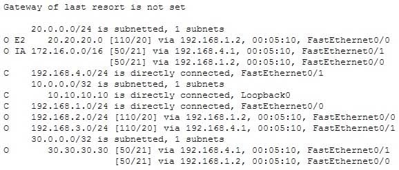
200-301 Part 11 Q10 109 Which of the following statements is FALSE?
- The route to 30.30.30.30 uses a cost of 21
- The command ip route 192.168.2.0 255.255.255.0 172.16.14.2 200 will replace the current route to 192.168.2.0/24
- The route to 192.168.2.0/24 uses the default administrative distance
- Traffic will be load balanced across two routes to 30.30.30.30
Explanation:
The command ip route 10.10.10.0 255.255.255.0 172.16.14.2 200 will NOT replace the current route to 10.0.0.0/24.When you execute the ip route command to enter a static route, the administrative distance can be altered by adding the desired distance value to the end of the command. In this scenario, the administrative distance value was set to 200. The route to the 10.10.10.0/24 network that is currently in the table was learned by OSPF and is using the default administrative distance of 110. Since 110 is lower than 200, the new static route will not be added to the routing table UNLESS the current route becomes unavailable. The route to 30.30.30.30 does uses a cost of 21, as is indicated by the value on the right side of the forward slash within the brackets found in the route entry, [50/21].The route to 192.168.2.0/24 uses the default administrative distance. It was learned from OSPF, which has a default distance of 110. Its administrative distance is indicated by the value on the left side of the forward slash within the brackets found in the route entry, [110/20].
Traffic will be load balanced across two routes to 30.30.30.30 because they have equal cost of 21. This cost is indicated by the value on the right side of the forward slash within the brackets found in the route entry, [50/21].
Objective:
Routing Fundamentals
Sub-Objective:
Describe how a routing table is populated by different routing information sources -
Which of the following statements are NOT true, based on the output below?
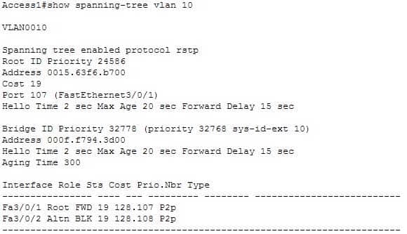
200-301 Part 11 Q11 110 - This switch is the root bridge.
- This switch has a priority of 32778.
- This switch has a MAC address of 0015.63f6.b700.
- All ports will be in a state of discarding, learning, or forwarding.
- All designated ports are in a forwarding state.
- This switch is using the default priority for STP
Explanation:
The upper half of the output provides information about the root bridge. It indicates that the root bridge has a bridge priority of 24586 and a MAC address of 0015.63f6.b700. The bottom half of the output pertains to the current switch, and indicates that this switch has a bridge priority of 32778 and a MAC address of 000f.f794.3d00.The value of the switch bridge priority is arrived at by adding the configured priority of 32768, which is indicated by the line priority 32768 sys-id-ext 10, to the VLAN ID of 10. Because 32768 is the default bridge priority for STP, this switch is set to the default priority for STP. The priority of this switch is 32778. The bridge priority is arrived at by adding the configured priority of 32768 to the VLAN ID of 10.This switch is not the root bridge, as indicated by the differences in priorities and MAC addresses between the root ID and the bridge ID output. If this were the root bridge, the MAC addresses and priority values would be the same in both the Root ID and the Bridge ID sections.
Finally, when a switch is using RSTP, as indicated by the output Spanning tree enabled protocol rstp, all ports will be in a state of discarding, learning, or forwarding, with all designated ports in a forwarding state. When RSTP has converged, all ports will be in either the discarding or forwarding states.
Objective:
LAN Switching Fundamentals
Sub-Objective:
Configure, verify, and troubleshoot STP protocols -
Which of the following values will be used by a router to make a routing decision when two routes have been learned from OSPF?
- cost
- administrative distance
- composite metric
- hop count
Explanation:
When two routes have been learned by OSPF to same network, the best route will be chosen based on lowest cost. Cost is the metric used in OSPF to choose the best route from all candidate routes learned through OSPF. Administrative distance is a measure of the trustworthiness of the routing information source. It is a value used by a router to choose between multiple known routes that have been learned from different routing sources, such as different routing protocols. When routes are learned from the same routing protocol, their administrative distance will be equal, and the router will then choose the route with the lowest metric value of the routing protocol. In this case, that metric is the OSPF cost. The composite metric is the metric used by EIGRP to choose a route when multiple routes have been learned by EIGRP.Hop count is the metric used by RIP to choose a route when multiple routes have been learned by RIP.
Objective:
Routing Fundamentals
Sub-Objective:
Describe how a routing table is populated by different routing information sources -
Which of the following IP addresses are valid Class B host addresses if a default Class B mask is in use? (Choose all that apply.)
- 10.6.8.35
- 133.6.5.4
- 192.168.5.9
- 127.0.0.1
- 190.6.5.4
-
What is the purpose of using the show arp command?
- To view the ARP statistics only for a particular interface
- To view details regarding neighboring devices discovered by ARP
- To view global ARP information such as timer and hold time
- To view the Address Resolution Protocol (ARP) cache
Explanation:
The show arp command is used to view the Address Resolution Protocol (ARP) cache. ARP is used by the Internet Protocol (IP) to find the Media Access Control (MAC) address or the hardware address of a host. The main function of ARP is to translate IP addresses to MAC addresses. The process of obtaining the address of a computer in the network is known as address resolution. This process is accomplished by sending an ARP packet from a source to a destination host. The destination host responds to the ARP packet by replying back to the source and including its own MAC address. Once the source host receives the reply, it will update its ARP cache with the new MAC address. The complete syntax of the show arp command is:show arp [ip-address [locationnode-id] | hardware-address [locationnode-id] | traffic [locationnode-id | interface-instance] | trace [error [locationnode-id] | dev [locationnode-id] | events [locationnode-id] table [locationnode-id] packets [locationnode-id] | [locationnode-id]] | type instance| [locationnode-id]The following is a brief description of the parameters used with this command:
ip-address: An optional parameter that displays specific ARP entries.
locationnode-id: An optional parameter that displays the ARP entry for a specific location. The method for entering the node-id argument is rack/slot/module notation.
hardware-address: An optional parameter that displays ARP entries that match the 48-bit MAC address.
traffic: An optional parameter that displays ARP traffic statistics.
interface instance: Either a physical interface instance or a virtual interface instance:
Physical interface instance: the naming notation is rack/slot/module/port and a slash mark between values is required as part of the notation where:
rack refers to the chassis number of the rack.
slot refers to the physical slot number of the line card.
module refers to the module number. A physical layer interface module (PLIM) is always 0.
port refers to the physical port number of the interface.
Virtual interface instance: the number range is variable depending on the type of interface.
trace: An optional parameter that displays the ARP entries in the buffer.
error: An optional parameter that displays the ARP error logs.
dev: An optional parameter that displays the ARP internal logs.
events: An optional parameter that displays the ARP events logs.
table: An optional parameter that displays the ARP cache logs.
packets: An optional parameter that displays the ARP packet receive and reply logs.
type instance: An optional parameter that specifies the interface for which you want to view the ARP cache.An example of the output of the show arp command is shown below along with a diagram of the network in which the router resides.
R1#show arp
Protocol Address Age (min) Hardware Addr Type Interface

Internet 192.0.5.1 120 0000.a710.4baf ARPA FastEthernet 0/1

Internet 192.0.5.6 105 0000.a710.859b ARPA FastEthernet 0/1

Internet 58.59.6.3 42 0000.a710.68cd ARPA FastEthernet 0/0

Internet 58.59.6.4 59 0000.0c01.7bbd ARPA FastEthernet 0/0
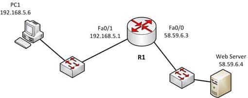
200-301 Part 11 Q14 111 From the information above, we can make the following conclusions about the actions R1 will take when it receives data from PC1 destined for the Web server:
– The data frames will be forwarded out the Fa0/0 interface of R1
– R1 will place the MAC address of the Web Server (0000.0c01.7bbd) in the destination MAC address of the frames
– R1 will put the MAC address if the forwarding Fa0/0 interface (0000.a710.68cd) in the place of the source MAC addressThe option stating that the show arp command is used to view the ARP statistics only for a particular interface is incorrect because this command is used to view the ARP cache. You can also view the information for a particular interface with the help of the interface instance parameter.
The options stating that the show arp command is used to view the details of neighboring devices discovered by the ARP or to view global ARP information, such as hold time and timer, are both incorrect because these are both Cisco Discovery protocol (CDP) functions, not ARP functions. The show cdp neighbors detail command is used to display details regarding the neighboring devices that are discovered by CDP, and the show cdp command displays global CDP information, such as timer and hold-time.
Objective:
Network Fundamentals
Sub-Objective:
Configure, verify, and troubleshoot IPv4 addressing and subnetting -
What are the three types of Internet Protocol version 6 (IPv6) addresses? (Choose three.)
- Unicast
- Broadcast
- Dual-cast
- Anycast
- Multicast
Explanation:
Unicast, multicast, and anycast are types of IPv6 addresses. The following are the IPv6 address types:- Unicast address: These types of addresses are used to define a single destination interface. A packet sent to a unicast address is delivered to the specific interface.
– Multicast address: These types of addresses are used to define a group of hosts. When a packet is sent to a multicast address, it is delivered to all the hosts identified by that address. Multicast addresses begin with the prefix FF00::/8 and the second octet identifies the range over which the multicast address is propagated. Some special case IPv6 multicast addresses:
– FF01:0:0:0:0:0:0:1: Indicates all-nodes address for interface-local scope.– FF02:0:0:0:0:0:0:2: Indicates all-routers address for link-local.
– Anycast address: These types of addresses are used to identify a set of devices. These addresses are also assigned to more than one interface belonging to different nodes. A packet sent to an anycast address is delivered to just one of the interfaces, based on which one is closest. For example, if an anycast address is assigned to a set of routers, one in India and another in the U.S., the users in the U.S. will be routed to U.S. routers and the users in India will be routed to a server located in India.The broadcast option is incorrect because these types of addresses are not supported by IPv6. Broadcast functionality is provided by multicast addressing.
The dual-cast option is incorrect because this is not a valid Cisco address type.
Objective:
Network Fundamentals
Sub-Objective:
Compare and contrast IPv6 address types -
Which media access control method is used by Ethernet technology to minimize collisions in the network?
- CSMA/CD
- token passing
- back-on algorithm
- full-duplex
Explanation:
Carrier Sense Multiple Access – Collision Detection (CSMA/CD) is used by Ethernet technology to minimize collisions in the network. The CSMA/CD method uses a back-off algorithm to calculate random time for retransmission after a collision. When two stations start transmitting at the same time, their signals will collide. The CSMA/CD method detects the collision, and both stations hold the retransmission for a certain amount of time that is determined by the back-off algorithm. This is an effort to help ensure that the retransmitted frames do not collide. Token passing is used by the token-ring network topology to control communication on the network. Full-duplex is the Ethernet communication mode that allows workstation to send and receive simultaneously. With the use of full-duplex, the bandwidth of the station can effectively be doubled. Hubs are not capable of handling full-duplex communication. You need dedicated switch ports to allow full-duplex communication.The back-on algorithm is an invalid option. There is no such contention method.
Objective:
LAN Switching Fundamentals
Sub-Objective:
Describe and verify switching concepts -
On which of the following networks will OSPF elect a designated router (DR)? (Choose two.)
- Broadcast
- NBMA
- Point-to-point
- Point-to-multipoint
Explanation:
OSPF will perform an election for a designated router (DR) and backup designated router (BDR) on every multi-access network segment. Multi-access segments are defined as segments where more than two hosts can reach each other directly, such as a shared Ethernet segment (broadcast multi-access) or Frame Relay (non-broadcast multi-access, or NBMA).DR and BDR elections do not occur on point-to-point or point-to-multipoint segments. Point-to-point and point-to-multipoint segments are not considered multi-access segments. OSPF routers on these network types will establish an adjacency without a DR/BDR election.
Objective:
Routing Fundamentals
Sub-Objective:
Configure, verify, and troubleshoot single area and multi-area OSPFv2 for IPv4 (excluding authentication, filtering, manual summarization, redistribution, stub, virtual-link, and LSAs) -
You have a class C address range and are planning a network that has an average of 50 hosts per subnet.
How many host bits will have to be borrowed for subnetting so that the maximum number of subnets can be implemented?
- 1
- 2
- 3
- 4
- 6
Explanation:
A class C address has 8 bits in host space. By using 2 bits from the host space for subnetting, leaving 6 host bits, you can create subnets that can accommodate up to 62 hosts each (26 – 2 = 62). This will ensure that the requirement of 50 hosts per subnet is met and the maximum number of subnets is provided.The formulas to calculate the number of subnets and hosts are:Number of subnets = 2number-of-subnet-bits
Number of hosts per subnet = 2number-of-host-bits – 2If you take 1 bit for subnetting:
Number of subnets = 21 = 2
Number of hosts per subnet = 27 – 2 = 126This results in a mask of 255.255.255.128 or /25. Since each subnet need not be bigger than 50, this solution would not maximize the number of subnets.
If you take 2 bits for subnetting:
Number of subnets = 22 = 4
Number of hosts per subnet = 26 – 2 = 62This results in a mask of 255.255.255.192 or /26. This solution would create more subnets, but the subnets are smaller than the requirement.
If you take 3 bits for subnetting:
Number of subnets = 23 = 8
Number of hosts per subnet = 25 – 2 = 30This results in a mask of 255.255.255.224 or /27. This would create more subnets, but the subnets are smaller than the requirement.
If you take 4 bits for subnetting:
Number of subnets = 24 = 16
Number of hosts per subnet = 24 – 2 = 14This results in a mask of 255.255.255.240 or /28. This solution would create more subnets, but the subnets are smaller than the requirement.
If you take 6 bits for subnetting:
Number of subnets = 26 = 64
Number of hosts per subnet = 22 – 2 = 2This mask, 255.255.255.252 or /30, yields only 2 IP addresses, but is quite commonly used on a point-to-point link, such as between two routers. This solution would create more subnets, but the subnets are smaller than the requirement.
You will always subtract 2 from the number of hosts (the formula of 2number-of-host-bits – 2) because the all-zeros bit address is reserved for the network address and the all-ones bit address is reserved for the broadcast address.
Prior to Cisco IOS Software Release 12.0, it was common practice to subtract 2 from the networks formula (2number-of-subnet-bits) to exclude addresses of all 1s and all 0s (called the all-ones subnet and subnet zero). Today that range is usable, except with some legacy systems. On certain networks with legacy software, you may need to use the previous formula (2n – 2) to calculate the number of subnets.
Objective:
Network Fundamentals
Sub-Objective:
Apply troubleshooting methodologies to resolve problems -
Which Cisco Internetwork Operating System (IOS) command is used to assign a router a name for identification?
- description
- banner motd
- hostname
- banner exec
Explanation:
The hostname command is used to assign the router a name for identification. This command is a global configuration mode command. The syntax of the command is as follows:Router(config)# hostname [name]
The name parameter of the command specifies the new host name for the router.
The description command is incorrect because this command is used to set a description for an interface. The description command is an interface configuration mode command.
The banner motd command is used to specify a message of the day (MOTD) banner to users logging into the router. This is a global configuration mode command, but it does not assign a name to the router for identification.
The banner exec command enables a banner message to be displayed when an EXEC process is created; for example, if a line is activated or an incoming connection is made to a telnet line.
Objective:
Infrastructure Management
Sub-Objective:
Configure and verify initial device configuration -
A new trainee is setting up a router in a test lab, and he asks you to describe the use of the connector marked BRI on the router.
Which is a correct use for this connecter?
- A WAN interface for a T1 connection
- A LAN interface to connect to a switch
- An interface to connect a console cable
- A WAN interface for an ISDN connection
Explanation:
The connector marked BRI is used for an Integrated Services Digital Network (ISDN) connection, specifically a basic rate interface (BRI). An ISDN basic rate interface provides three channels: a D channel for control signaling, and two B or bearer channels for data, resulting in 128 bits of bandwidth. A WAN interface for a T1 connection would be connected to a serial port on the router, not the BRI interface. It would not accept a basic rate ISDN connection.A LAN interface to connect to a switch would be an Ethernet connection that used either an RJ-45 connector or a legacy AUI connector. It would not accept a basic rate ISDN connection
An interface to a console connector will look like an RJ-45 Ethernet connector but will only accept a console or rollover cable, and is used to manage the router. It would not accept a basic rate ISDN connection.
These various ports can be seen on the backplane of a router as shown below:

200-301 Part 11 Q20 112 Objective:
WAN Technologies
Sub-Objective:
Describe WAN access connectivity options