200-301 : Cisco Certified Network Associate (CCNA) : Part 12
-
Which Cisco IOS command can be issued on a router to test the connectivity of one interface from another interface on the same router?
- ping (with no address specified)
- ping (with an address specified)
- tracert
- traceroute
Explanation:
The extended ping Cisco IOS utility, which is issued with no address specified, can be issued on a router to test connectivity between two remote routers. The ping utility uses Internet Control Messaging Protocol (ICMP) packets. An ICMP echo request is sent to the destination host. Upon its receipt, the destination host responds to the sending host with an ICMP echo reply. When the echo reply is received, the connectivity is verified. Below is sample output of the extended ping command:
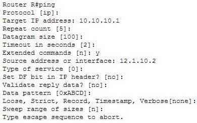
200-301 Part 12 Q01 113 The ping command with an address specified is incorrect because you when you issue this command you will either receive a reply from the destination or a destination unreachable message. It will not prompt for additional information as shown which is what allows you to specify the endpoints for the ping.
The traceroute command is not correct for this scenario because this command traces the path between the host issuing the command and the target network.
The tracert command is not a Cisco IOS command, but a Microsoft command.
Objective:
Routing Fundamentals
Sub-Objective:
Configure, verify, and troubleshoot IPv4 and IPv6 static routing -
Which of the following statements best describes the result of issuing the command standby 44 timers 3 1 on an HSRP router?
- The holdtime will be set to a value of 3, and the hellotime will be set to a value of 1.
- The status of the standby router will be displayed as unknown expired.
- The role of active router will be passed repeatedly from one router to another.
- The router will be configured to reassume the role of active router in the event that the router fails and is subsequently restarted.
Explanation:
When the command standby 44 timers 3 1 is issued on a Hot Standby Routing Protocol (HSRP) router, the role of active router will be passed repeatedly from one router to another. This behavior occurs when the timers are set incorrectly. The syntax for the standby timers command is standby [group-number] timers [hellotime holdtime].The hellotime variable is the number of seconds between hello messages and is set to a value of 3 by default.
The holdtime variable is the number of seconds that the HSRP standby router will wait before assuming that the active router is down; if the standby router believes the active router to be down, it will assume the role of active router.
The holdtime is set to a value of 10 by default. The holdtime should be set to a value at least three times the value of the hellotime. Otherwise, the active router might not be able to respond before the standby router assumes that the active router is down and becomes the new active router.
Because the command standby 44 timers 3 1 sets the hellotime to a value of 3 and the holdtime to a value of 1, the role of active router will be passed from one standby router to the next. To set the holdtime to a value of 3 and the hellotime to a value of 1, the command standby 44 timers 1 3 should be issued. To reset the timer values to their default values, the command no standby group-number timers should be issued.
The status of the standby router will be displayed as unknown expired if a Physical layer problem exists. The unknown expired status can also be displayed if only one HSRP router is configured for the subnet.
To configure an HSRP router to reassume the role of active router in the event that the router fails and is subsequently restarted, the command standby group-number preempt should be issued. When the HSRP active router fails or is shut down, the standby router assumes the role of active router. By default, when the original HSRP active router is restarted, it does not take the role of active router away from the original standby router, even if the original active router has a higher priority value. The command standby group-number preempt changes this default behavior.
The holdtime will not be set to a value of 3, and the hellotime will not be set to a value of 1. On the contrary, the hellotime will be set to a value of 3 and the holdtime will be set to a value of 1.
Objective:
Infrastructure Services
Sub-Objective:
Configure, verify, and troubleshoot basic HSRP -
You have executed the following commands on switch55:

200-301 Part 12 Q03 114 What is the result of executing the given commands? (Choose two.)
- Only the listed RADIUS server is used for authentication
- 802.1X authentication is enabled on the Fa0/1 interface only
- The key for the RADIUS server is firstKey111
- AAA is not enabled on the switch
Explanation:
As a result of executing these commands, the default list is used for the RADIUS server for authentication, and the key for the RADIUS server is firstKey111.A RADIUS server combines the authentication and authorization processes. Before you configure the RADIUS server, you should enable AAA by using the aaa new-model command in global configuration mode. Then, you can specify the location of the RADIUS server and the key using the radius-server host command. In this case, the RADIUS server is located at the IP address 192.168.105.67 and requires the key firstKey111 as the encryption key. This key must be mutually agreed upon by the server and the clients.
The aaa authentication dot1x default group radius command creates a method list for 802.1X authentication. The default group radius keywords specify that the default method will be to use all listed RADIUS servers to authenticate clients. Since only one is listed, it will be the only one used.
It is incorrect to state that 802.1X authentication is enabled only on the Fa0/1 interface. The interface range Fa 0/1 – 11 and the dot1x port-control auto commands specify that 802.1X authentication is enabled on the interfaces Fa0/1 to Fa0/11.
It is incorrect to state that AAA is not enabled on the switch. The aaa new-model command enables AAA globally on the switch.
Objective:
Infrastructure Security
Sub-Objective:
Describe device security using AAA with TACACS+ and RADIUS -
What port types are available for Rapid Spanning Tree Protocol (RSTP) but NOT available in Spanning Tree Protocol (STP)? (Choose two.)
- Root port
- Backup port
- Alternate port
- Designated port
- Learning port
Explanation:
RSTP was developed to reduce the high convergence times required in STP, and introduces the alternate port and backup port roles. RSTP is an Institute of Electrical and Electronics Engineers (IEEE) standard, 802.1w, and is interoperable with 802.1d (STP). It operates on the Data Link layer of the OSI model.An alternate port is a port that has an alternative path or paths to the root bridge, but is currently in a discarding state. A backup port is a port on a segment that could be used to reach the root port, but there is already an active designated port for the segment. An alternate port can also be described as a secondary, unused root port, and a backup port as a secondary, unused designated port.
A root port is a port on non-root switches used to reach the root switch. There can be only one root port on a switch, and it is determined by the least path cost to the root switch. Root ports are used in STP and RSTP.
A designated port is the port used by a network segment to reach the root switch. Designated ports lead away (downstream) from the root switch, and are determined by the lowest path cost to the root switch. While a switch can only have one root port, every other port could potentially be a designated port. Whenever a network segment could be serviced by more than one switch, STP will elect one switch as designated for the segment, and the other(s) will be blocking. This is a core function of the STP protocol, in that only one active Layer 2 path can exist between any two network segments. This port type is available in STP.
A learning port is not a valid port type in STP or RSTP. Learning is one of the possible port states in STP and RSTP. STP has five port states; blocked, listening, learning, forwarding, and disabled. There are only three port states in RSTP; discarding, learning, and forwarding.
Objective:
LAN Switching Fundamentals
Sub-Objective:
Configure, verify, and troubleshoot STP-related optional features -
Which of the following is a classful routing protocol?
- RIPv1
- EIGRP
- BGPv4
- RIPv2
Explanation:
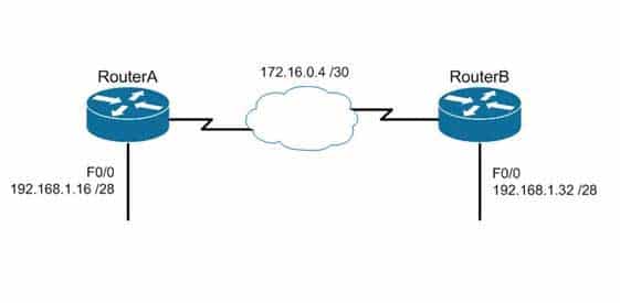
The Routing Information Protocol version 1 (RIPv1) is a classful routing protocol, which exchanges routes without including any subnet masking information. IP addresses in the routing table should have the same subnet mask. Because classful routing protocols may not fully utilize the available IP address range, all router interfaces within the same network must have the same subnet mask.Open Shortest Path First (OSPF), Routing Information Protocol version 2 (RIPv2), Enhanced Interior Gateway Routing Protocol (EIGRP), and Border Gateway Protocol version 4 (BGPv4) are classless routing protocols. These protocols include the subnet mask in the route advertisement and support variable length subnet masks (VLSM). Intermediate System-to-Intermediate System (IS-IS) is also a classless routing protocol. An example of a network using VLSM is shown below. Note the different masks used, indicated with CIDR notation.
200-301 Part 12 Q05 115 Objective:
Routing Fundamentals
Sub-Objective:
Compare and contrast distance vector and link-state routing protocols -
You have the following configuration on your router:
ip dhcp pool POOLNAME
network 10.1.0.0 255.255.255.0
default-router 10.1.0.254
dns-server 10.1.0.200
What command would you run to prevent the last available IP address in the scope from being allocated to a host via DHCP?
- ip dhcp restrict 10.1.0.254
- ip dhcp excluded-address 10.1.0.253
- ip dhcp excluded-address 10.1.0.254
- ip dhcp 10.1.0.253 excluded-address
Explanation:
In this scenario, you would run the ip dhcp excluded-address 10.1.0.253 command in global configuration mode to prevent DHCP allocation of the last available IP address in the scope. The ip dhcp excluded-address command is used to prevent DHCP from handing out IP addresses that are already statically configured on your network. The command can include a single IP address to exclude, or an entire range, such as:Router(config)# ip dhcp excluded-address 10.1.0.100 10.1.0.125
The command above would block the entire range of 10.1.0.100 through 10.1.0.125 from being allocated by DHCP. If the next IP address in sequence to be assigned would have been 10.1.0.100, DHCP will skip the range and assign 10.1.0.126 as the next host address.
You would not execute ip dhcp excluded-address 10.1.0.254. This is the address of the router and it will automatically be excluded.
The other commands are incorrect because they are not valid Cisco IOS commands.
Objective:
Infrastructure Services
Sub-Objective:
Configure and verify DHCP on a router (excluding static reservations) -
How many IP addresses are available for hosts in the 192.168.16.64 /26 subnet?
- 14
- 30
- 62
- 126
Explanation:
There are 62 IP addresses available for hosts in the 192.168.16.64 /26 subnet.The number of host addresses is calculated as 2n – 2, where n is the number of host bits and 2 is subtracted to exclude the network address and the broadcast address.
An IP address has 32 available bits divided into four octets. In the 192.168.16.66 /26 address, the /26 indicates that there are 26 masking bits, or that 26 bits are reserved for the network portion of the address. This leaves 6 bits for the host addresses (32 – 26 = 6).
The following formula is used to calculate the number of IP addresses available for hosts:
Network address: 192.168.16.0
Subnet mask in decimal: 255.255.255.192
Subnet mask in binary: 11111111.11111111.1111111.11000000
Number of bits used for masking = 26
Number of hosts bits in the address = 6Using the formula for calculating the number of hosts per subnet, we find:
Hosts formula: 2number-of-host-bits – 2
Hosts: 26 – 2 = 62For subnet 192.168.16.64, the valid host range starts from 192.168.16.65 and runs to 192.168.16.126. For subnet 192.168.16.128, the valid host range starts from 192.168.16.129 and runs to 192.168.16.190.
The options 14, 30, and 126 are incorrect because 62 IP addresses are available for hosts in the 192.168.16.64/26 subnet.
The correct mask for the size network desired is critical to proper network function. For example, assume a router has an interface Fa0/0 hosting a LAN with 20 computers configured as shown in the following output of show interfaces command:
Router# show interfaces
Fastethernet0 is up, line protocol is up
Hardware address is 000b.12bb.4587
Internet address 192.168.10.30/30
In this example, the computers will not be able to access anything beyond the LAN because the mask /30 only allows for 2 addresses when 21 (including the router interface) are required.
Objective:
Network Fundamentals
Sub-Objective:
Apply troubleshooting methodologies to resolve problems -
Refer to the following sample output:
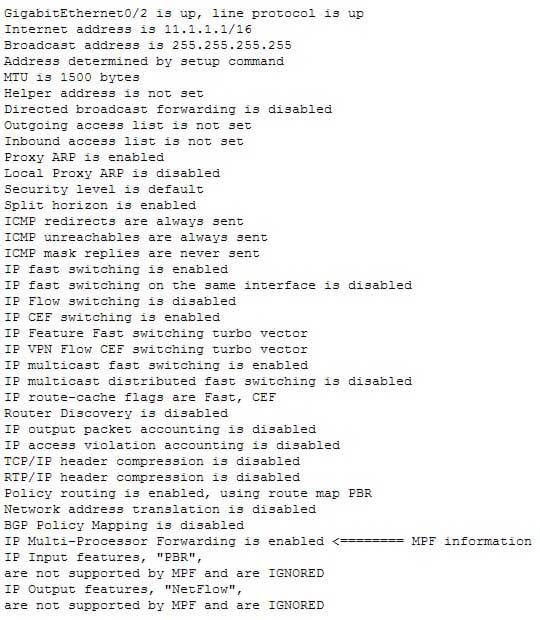
200-301 Part 12 Q08 116 Which Cisco Internetwork Operating System (IOS) command produces this output?
- show interfaces
- show interfaces summary
- show ip interface
- show interfaces serial
Explanation:
The show ip interface command will produce the displayed output. The show ip interface command is used to view the usability status of Internet Protocol (IP) interfaces. The complete syntax of this command is:show ip interface [type number] [brief]
Following is a brief description of the parameters used in this command:
type: An optional parameter that refers to the type of interface.
number: An optional parameter that refers to the interface number.
brief: An optional parameter used to view a summarized display of the usability status information for every interfaceThe show interfaces command does not generate the displayed output. This command is used to view information regarding statistics for specific interfaces.
The show interfaces summary command does not generate the displayed output. This command provides a summarized view of all interfaces configured on a device.
The show interfaces serial command does not generate the displayed output. This command is used to view information for a serial interface.
Objective:
LAN Switching Fundamentals
Sub-Objective:
Troubleshoot interface and cable issues (collisions, errors, duplex, speed) -
Which Cisco Internetwork Operating System (IOS) command is used to view the VLAN Trunking Protocol (VTP) statistics information?
- show vtp status
- show vtp domain
- show vtp statistics
- show vtp counters
Explanation:
The show vtp counters command is used to view VTP statistics information. The syntax of the command is as follows:show vtp {counters | status}
The parameters used in the command are counters, which specifies VTP statistics information, and status, which specifies VTP domain status information.
The following is the output of the show vtp counters command:
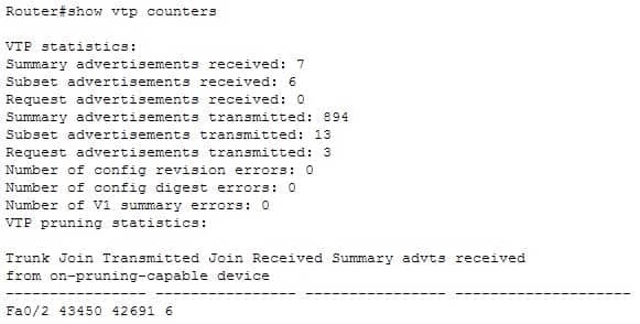
200-301 Part 12 Q09 117 The show vtp status command option is incorrect because this command is used to view VTP domain status information.
The show vtp domain and show vtp statistics commands are invalid options because they are not valid Cisco IOS commands.
Objective:
Routing Fundamentals
Sub-Objective:
Configure, verify, and troubleshoot inter-VLAN routing -
You are the network administrator for your company. The Chief Technical Officer of the company is looking for a routing solution that satisfies the following requirements:
– No routing protocol advertisements
– Increased network security
– No routing protocol overhead
– Not concerned about fault toleranceWhich of the following routing techniques matches the criteria?
- Dynamic routing
- Hybrid routing
- Static routing
- Public routing
Explanation:
The static routing technique matches the criteria given in this scenario. Static routing is a process of manually entering routes into a routing table. Static routes are not recommended for large networks because static routes are manually configured on the router. However, if a single link is used to connect an enterprise to an Internet Service Provider (ISP), then static routing is the best option.The following are characteristics of static routing:
– Configuring static routes does not create any network traffic.
– Manually configured static routes do not generate routing updates and therefore do not consume any network bandwidth.
– Router resources are used more efficiently.
– Static routes are not recommended for large networks because they are manually configured on the router and maintaining the routes can become problematic.
– Static route configuration is not fault tolerant, because static routes do not automatically adapt to changes in the network.The dynamic routing option is incorrect because route updates consume bandwidth and overhead. While the scenario is not concerned with routing protocol overhead, it states that there should be no bandwidth consumption by route advertisements.
Hybrid routing and public routing are not valid routing techniques in Cisco terminology.
Objective:
Routing Fundamentals
Sub-Objective:
Compare and contrast static routing and dynamic routing -
Which of the following statements are TRUE regarding the following output? (Choose all that apply.)
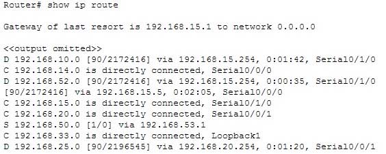
200-301 Part 12 Q11 118 - There are four default routes on this router.
- There are four physically connected interfaces on this router.
- This router is running EIGRP.
- The metric for the routes learned via a routing protocol is 90.
- A packet for the 192.168.52.0 network will be load-balanced across two paths.
Explanation:
This router is running EIGRP and a packet for the 192.168.52.0 network will be load-balanced across two paths.EIGRP routes display with a D code in the leftmost column of the show ip route command. The D stands for Diffusing Update Algorithm (DUAL), which is the algorithm used by EIGRP to determine the best and potential backup paths to each remote network. There are four EIGRP-learned routes in this exhibit.
When two routes with equal metrics exist in the routing table, EIGRP will send packets using both paths. In the output there are two routes listed for the 192.168.52.0 network. Both have the same metric value (2172416). Therefore, packets will be sent to that network via the Serial 0/1/0 interface to the neighbor at 192.168.15.254 and via the Serial 0/0/0 interface to the neighbor at 192.168.15.5. Both paths, either directly or indirectly, lead to the 192.168.52.0 network, and both paths have the same cost.
There are not four default routes on this router. The D represents EIGRP-learned routes, not default routes. There is one default route, as indicated by the line of output that says Gateway of last resort is 192.168.15.1 to network 0.0.0.0. Because Serial0/1/0 is directly connected to the 192.168.15.0 network, packets that are destined for networks not found in the routing table will be sent out on that interface.
The C in the leftmost column of the show ip route command represents directly connected networks, of which there are four in the exhibit. Closer examination, however, reveals that one of these entries (for network 192.168.33.0) is connected to a loopback interface (Loopback1), as opposed to a physical interface:
C 192.168.33.0 is directly connected, Loopback1
Loopback interfaces are virtual, software interfaces that appear in the routing table, but do not represent a physical interface on the router. Therefore, there are three physically connected interfaces on this router, not four.
The metric for the routes learned via a routing protocol is not 90. The 90 in the scenario output is the administrative distance (AD) of the route, and the 2196545 is the metric value (see below):
D 192.168.25.0 [90/2196545] via 192.168.20.254, 0:01:20, Serial0/0/1
Objective:
Routing Fundamentals
Sub-Objective:
Interpret the components of routing table -
You are purchasing a device to upgrade your network. You need to determine the type of device required, as well as the number and type of required interfaces. The device will host three LAN subnets and a T1 Internet connection.
Which of the following device and interface combinations will support this requirement without providing any unnecessary interfaces or using subinterfaces?
- a switch with one Ethernet interface and three serial interfaces
- a router with one serial interface and three Ethernet interfaces
- a router with one serial interface and one Ethernet interface
- a switch with one modem and three serial interfaces
Explanation:
This deployment will require a router with one serial interface and three Ethernet interfaces. When LAN subnets and the Internet must be connected, you must deploy a device that can make decisions based on IP addresses. This is the function of a router. Each LAN subnet will require a separate Ethernet interface, and the T1 connection requires a serial interface, so the router must have one serial interface and three Ethernet interfaces.A switch cannot be used to connect separate subnets and the Internet. This requires a router. Switches make forwarding decisions based on MAC addresses. In this deployment, decisions must be made on the basis of IP addresses. Moreover, switches only have Ethernet interfaces, so a switch could not handle the T1 connection.
A router with one serial and one Ethernet interface will not be sufficient. Each LAN subnet will require a separate Ethernet interface.
Objective:
Network Fundamentals
Sub-Objective:
Describe the impact of infrastructure components in an enterprise network -
Assume that all ports on Layer 2 devices are in the same Virtual LAN (VLAN). View the given network topology. (Click the Exhibit(s) button.)
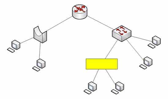
200-301 Part 12 Q13 119 Which network device should be placed at the highlighted box to produce a total of two broadcast domains and seven collision domains in the network?
- Hub
- Bridge
- Switch
- Router
Explanation:
A hub should be placed at the highlighted box to produce a total of two broadcast domains and seven collision domains in the network. Network devices segment collision domains and broadcast domains in the following manner:
– Hub: A Layer 1 device with all ports in same collision domain and broadcast domain.
– Bridge/Switch: Layer 2 devices on which all ports are in different collision domains, but in the same broadcast domain (assuming that all ports are in the same VLAN or no VLAN is configured).
– Routers: A Layer 3 device on which every port is a separate collision as well as broadcast domain.The bridge shown in the graphic has three ports populated by active links, resulting in three collision domains. The switch shown in the exhibit has four ports populated with the links, resulting in four collision domains. Together these two devices create seven collision domains.
Because the scenario requires that there be no more than seven collision domains, the device in the highlighted box must not create any further collision domains. A hub is a device that has all its ports in the same collision domain and will not create any further collision domains in the topology.A bridge or switch cannot be the correct option because these will also add collision domains.
In the exhibit, the router has two ports with active links, which will result into two broadcast domains. Because the scenario states there are no more than two broadcast domains, the device in the highlighted box must not be a router. Routers are used to segment broadcast domains.
Objective:
Network Fundamentals
Sub-Objective:
Describe the impact of infrastructure components in an enterprise network -
Which Cisco IOS command is used on a Catalyst 2950 series switch to verify the port security configuration of a switch port?
- show interfaces port-security
- show port-security interface
- show ip interface
- show interfaces switchport
Explanation:
The show port-security interface command displays the current port security and status of a switch port, as in this sample output:

200-301 Part 12 Q14 120 The sample output indicates that port security has been enabled on interface FastEthernet0/1, and that a maximum of two MAC addresses has been configured. A violation policy of Shutdown indicates that if a third MAC address attempts to make a connection, the switch port will be disabled.
The violation mode setting has three possible values that take the following actions when a violation occurs:
– protect Drops packets with unknown source addresses until you remove a sufficient number of secure MAC addresses to drop below the maximum value.
– restrict Drops packets with unknown source addresses until you remove a sufficient number of secure MAC addresses to drop below the maximum value and causes the Security Violation counter to increment. It will send a Syslog message and an SNMP trap as well.
– shutdown Puts the interface into the error-disabled state immediately and sends an SNMP trap notificationThe show ip interface command is incorrect because it displays protocol-related information about an interface, and nothing pertaining to switch port security.
The show interfaces switchport command is incorrect because it displays non-security related switch port information, such as administrative and operational status and trunking.
The show interfaces port-security command is incorrect because this is not a valid Cisco command.
Objective:
Infrastructure Security
Sub-Objective:
Configure, verify, and troubleshoot port security -
You wish to configure Secure Shell (SSH) support on your router so that incoming VTY connections are secure.
Which of the following commands must be configured? (Choose all that apply.)
- ip domain-name
- transport input ssh
- ip access-group
- crypto key generate rsa
- service config
Explanation:
Secure Shell (SSH) provides a secure alternative to Telnet for remote management of a Cisco device. Configuring Secure Shell (SSH) support on a Cisco router involves a minimum of three commands:
– ip domain-name [domain-name]: configures the DNS of the router (global configuration mode)
– crypto key generates rsa: generates a cryptographic key to be used with SSH (global configuration mode)
– transport input ssh: allows SSH connections on the router’s VTY lines (VTY line configuration mode)The transport input ssh command allows only SSH connectivity to the router, and prevents clear-text Telnet connections. To enable both SSH and Telnet, you would use the transport input ssh telnet command.
The ip access-group command is incorrect because this command is used to activate an access control list (ACL) on an interface, and does not pertain to SSH.
The service config command is incorrect because this command is used to automatically configure routers from a network server, and does not pertain to SSH.
Objective:
Infrastructure Security
Sub-Objective:
Configure, verify, and troubleshoot basic device hardening -
Which command would be used to establish static translation between an inside local address and an inside global address?
-
Router(config)# ip nat inside source static local-ip global-ip -
Router(config)# ip source nat inside static local-ip global-ip
-
Router(config)# ip nat inside static source local-ip global-ip
-
Router(config)# ip nat static inside source local-ip global-ip
Explanation:
You should use the following command:Router(config)# ip nat inside source static local-ip global-ip
You can translate your own IP addresses into globally unique IP addresses when communicating outside of your network. You can configure static or dynamic inside source translation.
To establish static translation between an inside local address and an inside global address, you should use the ip nat inside source static local-ip global-ip command. This static configuration can be removed by entering the no ip nat inside source static global command.
The other options are incorrect as they are not valid Cisco IOS configuration commands.
Objective:
Infrastructure Services
Sub-Objective:
Configure, verify, and troubleshoot inside source NAT -
-
Which Cisco Internetwork Operating System (IOS) command is used to assign a router a name for identification?
- description
- banner motd
- hostname
- banner exec
Explanation:
The hostname command is used to assign the router a name for identification. This command is a global configuration mode command. The syntax of the command is as follows:Router(config)# hostname [name]
The name parameter of the command specifies the new host name for the router.
The description command is incorrect because this command is used to set a description for an interface. The description command is an interface configuration mode command.
The banner motd command is used to specify a message of the day (MOTD) banner to users logging into the router. This is a global configuration mode command, but it does not assign a name to the router for identification.
The banner exec command enables a banner message to be displayed when an EXEC process is created; for example, if a line is activated or an incoming connection is made to a telnet line.
Objective:
Network Fundamentals
Sub-Objective:
Select the appropriate cabling type based on implementation requirements -
Which command is used to disable Cisco Discovery Protocol (CDP) on a Cisco router?
- disable cdp
- no cdp run
- no cdp enable
- no cdp advertise-v2
Explanation:
The no cdp run command is used to disable CDP on a Cisco router globally. CDP is a Layer 2 (Data Link layer) protocol that discovers information about neighboring network devices. CDP does not use network layer protocols to transmit information because it operates at the Data Link layer. Therefore, it is useful to determine information about directly connected Cisco network devices, because it can operate when network protocols have not been configured or are misconfigured. The show cdp neighbors detail command is used to view the IP addresses of the directly connected Cisco devices.The no cdp advertise-v2 command disables CDPv2 advertisements. It will not disable the protocol globally.
The no cdp enable command is used to disable CDP on an interface. In a situation where CDP needs to be disabled on a single interface only, such as the interface leading to the Internet, this command would be executed from interface configuration mode for that specific interface. It will not disable the protocol globally. For example, to disable CDP for only the serial0 interface, the command sequence would be:
Router#configure terminal
Router(config)#interface serial 0
Router(config-if)no cdp enable
The disable cdp command is not a valid Cisco command.
Objective:
LAN Switching Fundamentals
Sub-Objective:
Configure and verify Layer 2 protocols -
You are the network administrator for your company and have configured Cisco Discovery Protocol (CDP) in your network. You recently noticed that when devices send large numbers of CDP neighbor announcements, some devices are crashing. You decide to disable CDP on the router.
Which command should you use to achieve the objective?
- no cdp run
- set cdp disable
- no cdp enable
- no cdp advertise-v2
Explanation:
You should use the no cdp run command to disable CDP on the router. Due to a known vulnerability regarding the handling of CDP by Cisco routers and switches when devices send large numbers of CDP neighbor announcements, some devices can crash or cause abnormal system behavior. To overcome this problem, you can disable CDP for the entire router by using the no cdp run command.You cannot use the set cdp disable command to disable CDP on the router. This command disables CDP on an entire Catalyst switch.
You cannot use the no cdp enable command to disable CDP on the router. This command disables CDP on a specific interface.
You cannot use the no cdp advertise-v2 command to disable CDP on the router. This command disables CDPv2 advertisements.
Objective:
LAN Switching Fundamentals
Sub-Objective:
Configure and verify Layer 2 protocols -
You instructed your assistant to add a new router to the network. The routers in your network run OSPF. The existing router, OldRouter, is configured as follows:
router ospf 1
network 192.168.5.0 0.0.0.255 area 0
network 192.168.10.0 0.0.0.255 area 0
The OldRouter interface that connects to NewRouter is 192.168.5.3/24. Your assistant shows you the configuration that will be implemented:
newrouter(config)# router ospf 1
newrouter(config-router)# network 192.168.5.0 255.255.255.0 area 0
What is wrong with this configuration?
- The area ID is incorrectly configured.
- The wildcard mask is incorrectly configured.
- The network statement is incorrectly configured.
- The process ID number is incorrectly configured.
Explanation:
When entering network statements for OSPF, a wildcard mask is used instead of a regular mask. Since the network connecting the two routers is a class C network, as shown by the address 192.168.5.0/24, the wildcard mask should be 0.0.0.255 rather than 255.255.255.0. With wildcard masks, the 0s octets must match, and the 255s octets do not have to match.The area ID is correct. Old Router is in area 0, so New Router should be as well. There must be an area 0 in an OSPF network. There can be multiple areas as well, but they must all connect to area 0. If non-0 areas cannot be directly connected to area 0, they must be configured with a virtual link across an area that does connect to the backbone (area 0).
The network statement is correct. The network between the routers is 192.168.5.0.
The process ID number is correct. The number is stated as OSPF 1 on Old Router and OSPF 1 on New Router. They match in this case but that is not required. Process IDs are only locally significant.
Objective:
Routing Fundamentals
Sub-Objective:
Configure, verify, and troubleshoot single area and multi-area OSPFv2 for IPv4 (excluding authentication, filtering, manual summarization, redistribution, stub, virtual-link, and LSAs)