200-301 : Cisco Certified Network Associate (CCNA) : Part 14
-
You have a router that is not syncing with its configured time source.
Which of the following is NOT a potential reason for this problem?
- The reported stratum of the time source is 12
- The IP address configured for the time source is incorrect
- NTP authentication is failing
- There is an access list that blocks port 123
Explanation:
A reported stratum of 12 will not cause a router’s inability to synchronize with its configured time source. The stratum value describes the device’s distance from the clock source, measured in NTP server hops. When a router reports a stratum value over 15, it is considered unsynchronized. Therefore, a report of 12 could be normal.The other options describe potential reasons for a lack of synchronization.
When you are configuring the local router with a time source, if the IP address configured for the time source is incorrect, then no synchronization will occur.
If NTP authentication is configured between the local router and its time source, and that process is failing (for example, due to a non-matching key or hashing algorithm), then synchronization will not occur.
If there were an access list applied to any interface in the path between the local router and its time source that blocks port 123 (the port used for NTP), then synchronization will not occur.
Objective:
Infrastructure Services
Sub-Objective:
Configure and verify NTP operating in a client/server mode -
Which Cisco IOS command allows you to change the setting of the configuration register?
- boot config
- configuration-register edit
- config-register
- edit configuration-register
Explanation:
The config-register command is used to change the setting of the configuration register. The configuration register has the boot field setting, which specifies the order in which the router should look for bootstrap information. The router contains a 16-bit software register, which is stored in the non-volatile random access memory (NVRAM). The config-register command is used to modify the default configuration register. The most common use of changing this register is to instruct the router to ignore the stored configuration file and boot as a new router with no configuration. This process is normally used when a router has a password that is not known and must be reset. For security purposes, this procedure can only be performed from the console connection, which means it requires physical access to the router.Normally the setting of this register is 0x2102, which tells the router to look for a configuration file. If the file exists, it will use it. If none exists, the router will boot into ROM and present the user with a menu-based setup. This would be the default behavior for a new router as well.
To view the value of the configuration register, use the show version command as displayed below. The register setting can be seen at the bottom of the output in bold.
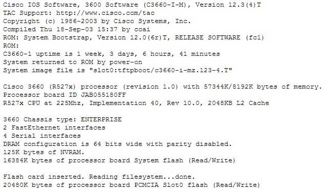
200-301 Part 14 Q02 130 Configuration register is 0x2102
To change this setting would require issuing these commands, followed by a restart:
Router#configure terminal
Enter configuration commands, one per line. End with CNTL/Z.
Router(config)#config
Router(config)#config-register 0x2142
By setting register to 0x2142, the router will ignore a configuration file at reboot if it exists. The router will then enter setup mode and prompt for you to enter initial system configuration information, as would happen with a new router. This enables the user to bypass an unknown password, since the password is contained in the file.
The boot config command is incorrect because this command is used to set the device where the configuration file is located (flash, slot, etc.) and file name for the configuration file, which helps the router to configure itself during startup.
The configuration-register edit command and the edit configuration-register commands are incorrect because they are not valid Cisco IOS commands.
Objective:
Infrastructure Management
Sub-Objective:
Perform device maintenance -
You are planning the configuration of an IPsec-protected connection between two routers. You are concerned only with the integrity of the data that passes between the routers. You are less concerned with the confidentiality of the data, and you would like to minimize the effect of IPsec on the data throughput.
Which protocol option should you choose?
- Authentication Header (AH) in tunnel mode
- Authentication Header (AH) in transport mode
- Encapsulating Security Payload (ESP) in tunnel mode
- Encapsulating Security Payload (ESP) in transport mode
Explanation:
You should choose Authentication Header (AH) in tunnel mode to meet the scenario requirements. Two protocols can be used to build tunnels and protect data traveling across the tunnel:
– Authentication Header (AH) uses protocol 51.
– ESP uses protocol 50.AH is defined in Request for Comments (RFC) 1826 and 2402. AH does not perform data encryption, and therefore information is passed as clear text. The purpose of AH is to provide data integrity and authentication, and optionally to provide anti-reply service. It ensures that a packet that crosses the tunnel is the same packet that left the peer device and no changes have been made. It uses a keyed hash to accomplish this.
ESP is defined in RFC 2406. ESP can provide data integrity and authentication, but its primary purpose is to encrypt data crossing the tunnel. On Cisco devices, ESP supports encryption using Advanced Encryption Standard (AES), Data Encryption Standard (DES), or Triple DES (3DES). Tunnel mode is used between Virtual Private Network (VPN) gateways such as routers, firewalls, and VPN concentrators.
You would not choose Authentication Header (AH) in transport mode. Transport mode is used between end stations or between an end station and a VPN gateway.
You would not choose Encapsulating Security Payload (ESP) in tunnel mode or transport mode. Using ESP will slow the connection because of the encryption and decryption process that will occur with each packet.
Objective:
WAN Technologies
Sub-Objective:
Describe WAN access connectivity options -
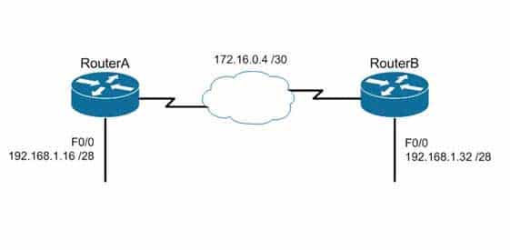
You are the Cisco administrator for Metroil. One of your assistants has submitted the given diagram as a potential addressing plan for two offices. Both offices use EIGRP as the routing protocol. You immediately see a problem with the proposal.
Which of the following actions could be a solution? (Choose two. Each correct option is a complete solution.)
200-301 Part 14 Q04 131 - Execute the no auto-summary command on both routers.
- Change the network on F0/0 of Router A to 192.168.3.0/24 and change the network on F0/0 of Router B to 192.168.2.0/24.
- Change the network on F0/0 of Router B to 192.168.1.48/28.
- Execute the auto-summary command on both routers.
Explanation:
You should either execute the no auto-summary command on both routers, or change the network on F0/0 of Router A to 192.168.3.10/24 and the network on F0/0 of Router B to 192.168.2.0/24. The exhibit is an example of discontiguous subnets, in which two subnets (192.168.1.16 and 192.168.1.32) of the same major network (192.168.1.0) are separated by a completely different network (172.16.0.4/30). The no auto-summary command instructs EIGRP to stop automatically summarizing advertised networks to their classful boundaries. Without the no auto–summary command, EIGRP will automatically summarize these two subnets to 192.168.1.0, and advertise the summary route across the WAN link, losing the subnet-specific information and causing routing problems. The no auto-summary command stops this behavior, and allows EIGRP to advertise specific subnets.An alternate solution would be to change the network on F0/0 of Router A to 192.168.3.0/24 and the network on F0/0 of Router B to 192.168.2.0/24. If that were done, the two networks would be in separate class C networks and auto summarization would not be a problem.
It would not help to change the network on F0/0 of Router B to 192.168.1.48/28. The two networks would still be in the same class C network and the summarization process would confuse routing.
It would not help to execute the auto-summary command. The command is already in effect by default.
Objective:
Routing Fundamentals
Sub-Objective:
Configure, verify, and troubleshoot EIGRP for IPv4 (excluding authentication, filtering, manual summarization, redistribution, stub) -
Which prompt indicates the configuration mode at which Cisco IOS debug commands can be issued?
-
router>
-
router# -
router(config)#
-
router(config-if)#
Explanation:
You would use privileged EXEC mode, as indicated by the router# prompt, to issue Cisco IOS show and debug commands. All debug commands are entered in privileged EXEC mode. A brief description of all the debugging commands can be displayed by entering the following command in privileged EXEC mode at the command line:debug?
Debugging output consumes high CPU processing power and can leave the system unusable. The debug commands should be reserved to troubleshoot specific problems, preferably with the help of Cisco technical support staff.
The prompt router> indicates user exec mode, which provides limited access to the router.
The prompt router(config)# indicates global configuration mode, which allows configuration settings affecting the entire router. Passing through this mode is also required to access configuration mode for specific interfaces as well.
The prompt router(config-if)# indicates interface configuration mode, which allows configuration of the interface specified when entering this mode.
Objective:
Infrastructure Management
Sub-Objective:
Configure and verify device management -
-
Which Cisco Internetwork Operating System (IOS) command can be used to configure the location of the configuration file?
- boot buffersize
- configure
- boot config
- service config
Explanation:
The boot config command will configure the location of the configuration file. It must be followed by the copy run start command to be effective at next reboot. The syntax of the command is as follows:boot config device:filename
The parameters of the command are as follows:
– Device : Specifies the device that contains the configuration file.
– Filename : Specifies the name of the configuration file.The boot buffersize command is incorrect because this command is used to modify the buffer size used to load the IOS image. Moreover, this command no longer functions in IOS 12.4.
The configure command is incorrect because this command is used to enter the global configuration mode.
The service config command is incorrect because this command is used to enable autoloading of configuration files from a network server.
Objective:
Infrastructure Management
Sub-Objective:
Perform device maintenance -
Refer to the following configuration on a Cisco router to allow Telnet access to remote users:
Router(config)#line vty 0 2
Router(config-line)#login
Router(config-line)#password guest
How many users can Telnet into this router at the same time?
- 0
- 1
- 2
- 3
- 5
Explanation:
The given configuration will allow three users to Telnet into the router at the same time. The line vty 0 2 command specifies a range from 0 to 2; therefore, three simultaneous Telnet sessions are allowed on this Cisco router. The commands in the exhibit can be explained as follows:Router(config)#line vty 0 2 (determines which of the five possible terminal lines are being configured. In this case, they are lines 0 through 2. It also determines the number of lines available, in that any line with no password configured will be unusable.)
Router(config-line)#login (specifies that a password will be required)
Router(config-line)#password guest (specifies the password)The default configuration allows five simultaneous Telnet sessions on the Cisco router. For the default configuration, you would issue the vty 0 4 command in global configuration mode.
You must configure a password when enabling a router for Telnet access. Without a password, the login access to the router will be disabled and you will receive the following error message if you try to Telnet to the router:
router# telnet 10.10.10.1
Trying 10.10.10.1 ... Open
Password required, but none set
[Connection to 10.10.10.1 closed by foreign host]
Objective:
Infrastructure Management
Sub-Objective:
Configure and verify device management -
Which of the following are characteristics of Enhanced Interior Gateway Routing Protocol (EIGRP)? (Choose all that apply.)
- Requires a hierarchical physical topology
- Does not require a hierarchical physical topology
- Uses Diffusing Update Algorithm (DUAL) to provide loop prevention
- Uses Bellman-Ford algorithm to provide loop prevention
- Supports Message-Digest Algorithm 5 (MD5) authentication
- Does not support Message-Digest Algorithm 5 (MD5) authentication
- Can differentiate between internal and external routes
- Uses a 32-bit metric
Explanation:
EIGRP does not require a hierarchical physical topology. It uses Diffusing Update Algorithm (DUAL) to provide loop prevention, and it supports Message-Digest Algorithm 5 (MD5) authentication. It can differentiate between internal and external routes, and uses a 32-bit metric.EIGRP is a classless protocol that allows the use of variable length subnet masks (VLSM) and supports classless interdomain routing (CIDR) for allocation of IP addresses. The following are characteristics of EIGRP:
– Supports large networks due to high scalability
– Provides fast convergence using the Diffusing Update Algorithm (DUAL)
– Performs equal and unequal load balancing by default
– Supports variable length subnet masks (VLSM) and classless interdomain routing (CIDR)
– Is a hybrid routing protocol (distance-vector protocol) that also provides link-state protocol characteristics
– Is a classless protocol
– Sends partial route updates only when there are changes, reducing bandwidth usage for routing updates
– Has an administrative distance of 90 for EIGRP internal routes, 170 for EIGRP external routes, and 5 for EIGRP summary routes
– Is used only with Cisco platforms
– Provides support for IP IPX and AppleTalk protocols
– Can differentiate between internal and external routes
– Uses a 32-bit metricEIGRP can load-balance up to four unequal cost paths. To do so, use the variance n command to instruct the router to include routes with a metric of less than n times the minimum metric route for that destination. The variable n can take a value between 1 and 128. The default is 1, which means equal cost load balancing.
The option stating that EIGRP requires a hierarchical physical topology is incorrect because EIGRP does not require or support a hierarchical routing topology.
The option stating that EIGRP uses Bellman-Ford algorithm to provide loop prevention is incorrect. EIGRP uses DUAL to provide loop prevention.
Objective:
Routing Fundamentals
Sub-Objective:
Configure, verify, and troubleshoot EIGRP for IPv4 (excluding authentication, filtering, manual summarization, redistribution, stub) -
You receive the following error message after addressing and enabling an interface:
%192.168.16.0 overlaps with FastEthernet0/0
Which two are NOT the causes of the error message? (Choose two.)
- incorrect subnet mask in the new interface
- incorrect IP address on the new interface
- incorrect encapsulation configured
- failure to issue the no shutdown command
Explanation:
The error message %192.168.16.0 overlaps with FastEthernet0/0 indicates that the newly configured interface is in the same subnet as an existing interface. This can occur if there is an incorrect subnet mask or an address that inadvertently places the new interface in that subnet. Each router interface must be in a different subnet to function. For example, when the series of commands below is executed on a router, it will elicit the error message because the two IP addresses used are in the same subnet given the subnet mask in use.Router#config t Router(config)#interface S0 Router(config-if)#ip address 192.168.1.17 255.255.255.0 Router(config-if)#no shutdown Router(config-if)interface S1 Router(config-if)#ip address 192.168.1.65 255.255.255.0 Router(config-if)#no shutdown 0%192.168.1.0 overlaps with Serial 0
It’s also a valuable skill to be able to recognize these problems before the router tells you about them. In the diagram below, you should be able to spot the problem with the two planned addresses on the router as being in the same subnet before you receive the error message.
An incorrect encapsulation would prevent the interface from working, but would not generate this message.
If the no shutdown command had not been issued, we would not be receiving this error. It is only generated when an attempt is made to enable an incorrectly configured interface.
Objective:
Routing Fundamentals
Sub-Objective:
Troubleshoot basic Layer 3 end-to-end connectivity issues -
You are the network administrator for your company. Your company has opened a new site in London. The Chief Technical Officer (CTO) of the company wants to implement a routing protocol that can provide the following features:
– Supports multiple large networks
– Does not require a hierarchical physical topology
– Supports VLSM
– Provides loop prevention and fast convergence
– Provides load balancing over un-equal cost linksWhich routing protocol should be implemented in the new site?
- Enhanced Interior Gateway Routing Protocol (EIGRP)
- Open Shortest Path First (OSPF)
- Interior Gateway Routing Protocol (IGRP)
- Interior Gateway Routing Protocol (IGRP)
Explanation:
Enhanced Interior Gateway Routing Protocol (EIGRP) is the routing protocol that should be implemented for this scenario. EIGRP is a classless protocol that allows the use of variable length subnet masks (VLSM) and classless interdomain routing (CIDR) for the allocation of IP addresses. The following are characteristics of EIGRP:
– Supports large networks due to high scalability.
– Does not require a hierarchical physical topology.
– Provides loop prevention and fast convergence by using Diffusing Update Algorithm (DUAL).
– Performs equal cost load balancing by default.
– Can be configured to perform unequal-cost load balancing.
– Supports VLSM and CIDR.
– Is a hybrid routing protocol (a distance-vector protocol that also provides link-state protocol characteristics).
– Is a classless protocol.
– Sends partial route updates only when there are changes.
– Supports Message-Digest algorithm 5 (MD5) authentication.
– Has an administrative distance is 90 for EIGRP internal routes, 170 for EIGRP external routes, and 5 for EIGRP summary routes.
– Is only used with Cisco platforms.All the other options are incorrect because they would not provide the features required in this scenario.
OSPF requires a hierarchical physical topology.
IGRP does not support VLSM.
RIPV2 is not designed for multiple large networks.
Objective:
Routing Fundamentals
Sub-Objective:
Compare and contrast distance vector and link-state routing protocols -
You have implemented SNMP v3 in your network. After making the configuration changes, you find that technicians in the TECHS group cannot access the MIB. You execute the show run command and receive the following output that relates to SNMP:
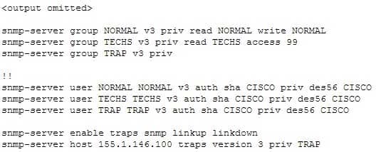
200-301 Part 14 Q11 132 What is preventing the TECHS group from viewing the MIB?
- The presence of the keyword priv in the command creating the RESTRICTED group
- A mismatch between the authentication mechanism and the encryption type in the command creating the TECHS user
- The absence of an access list defining the stations that can used by the TECHS group
- The presence of the keyword auth in the command creating the TECHS user
Explanation:
The command that creates the TECHS group ends with the parameter access 99:snmp-server group TECHS v3 priv read TECHS access 99
This indicates that the access list number 99 is specifying the IP addresses of the stations allowed to connect to the MIB for the group. Since the access list is missing from the configuration, no IP addresses will be allowed, and no connections can be made by the group.
The presence of the keyword priv in the command creating the TECHS group is not causing the issue. This keyword indicates that encryption (privacy) and authentication should both be used on all transmissions by the group.
In SMNPv3, there are three combinations of security that can be used:
– noAuthNoPriv- no authentication and no encryption; includes the noauth keyword in the configuration
– AuthNoPriv – messages are authenticated but not encrypted; includes the auth keyword in the configuration
– AuthPriv – messages are authenticated and encrypted; includes the priv keyword in the configurationThere is no mismatch between the authentication mechanism and the encryption type in the command creating the TECHS user.
snmp-server user TECHS TECHS v3 auth sha CISCO priv des56 CISCO
In the preceding command, the section auth sha CISCO specified that messages are authenticated using SHA with a key of CISCO. It does not need to the match the section priv des56 CISCO, which indicates that encryption (priv) will be provided using DES56 with a key of CISCO.
The presence of the keyword auth in the command creating the TECHS user is not causing the issue. This line indicates that that messages are authenticated using SHA with a key of CISCO.
Objective:
Infrastructure Management
Sub-Objective:
Configure and verify device-monitoring protocols -
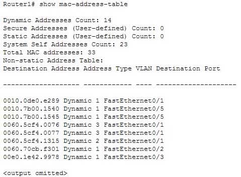
Based on the command output below, which of the interfaces on Router1 are trunk ports?
200-301 Part 14 Q12 133 - Fa0/1
- Fa0/2
- Fa0/3
- Fa0/5
Explanation:
Interface Fa0/1 is a trunk port. The output shows that it has MAC addresses that belong to VLANs 1, 2 and 3. Only trunk ports can carry traffic from multiple VLANs.Fa0/2 is not a trunk port. It only carries traffic from VLAN 1.
Fa0/3 is not a trunk port. It only carries traffic from VLAN 1.
Fa0/5 is not a trunk port. It only carries traffic from VLAN 1.
Objective:
Infrastructure Management
Sub-Objective:
Use Cisco IOS tools to troubleshoot and resolve problems -
Your company’s network must make the most efficient use of the IP address space. In the following diagram, the circles define separate network segments. The requirements of each network segment are given in the diagram. (Click the Exhibit(s) button.)
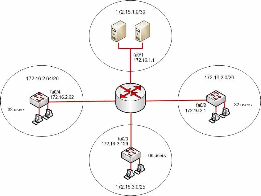
200-301 Part 14 Q13 134 Users complain of connectivity issues. You need to discover the problems with the network configuration.
What are the three problems with the network diagram? (Choose three.)
- The 172.16.1.0/30 segment requires more user address space.
- The 172.16.2.0/26 segment requires more user address space.
- The 172.16.3.0/25 segment requires more user address space.
- The 172.16.2.64/26 segment requires more user address space.
- Interface fa0/2 has an IP address that belongs to the 172.16.2.64/26 segment.
- Interface fa0/4 has an IP address that belongs to the 172.16.2.0/26 segment.
- Interface fa0/3 has an IP address outside the 172.16.3.0/25 segment.
Explanation:
The given exhibit has three problems:
– The 172.16.1.0/30 segment requires more user address space.
– Interface Fa0/4 has an IP address that belongs to the 172.16.2.0/26 segment.
– Interface Fa0/3 has an IP address outside the 172.16.3.0/25 segment.The 172.16.1.0/30 segment, as configured, will only support two hosts. This segment needs to support three hosts, the two servers, and the Fa0/1 interface. The number of hosts that a subnet is capable of supporting is a function of the number of host bits in the subnet mask. When that has been determined, the following formula can be used to determine the number of hosts yielded by the mask:
2n – 2 = X
(where n = the number of host bits in the mask and X = the number of hosts supported)In this example with a 30-bit mask, 2 host bits are left in the mask. When that is plugged into the formula, it yields only two usable addresses. The -2 in the formula represents the two addresses in each subnet that cannot be assigned to hosts, the network ID and the broadcast address. Therefore, the segment should be configured with the 172.16.1.0/29 address range, which supports up to six hosts.
Interface fa0/4, as configured, has an IP address that belongs to the 172.16.2.0/26 segment. With a 26-bit mask and the chosen class B address, the following network IDs are created:
172.16.0.0
172.16.0.64
172.16.1.128
172.16.1.192
172.16.2.0
172.16.2.64
172.16.2.128
172.16.2.192
172.16.2.0
172.16.2.64
172.16.2.128
172.16.2.192
…and so on, incrementing each time by 64 in the last octetThe 172.16.2.0/26 segment is allocated host addresses in the 172.16.2.1 through 172.16.2.62 range (the last address, 172.16.2.63, is the broadcast address and cannot be assigned). Interface fa0/4 should be assigned an IP address in the 172.16.2.64/26 range, which includes host addresses in the 172.16.2.65 through 172.16.2.126 range.
Interface Fa0/3, as configured, has an IP address outside the 172.16.3.0/25 segment. With a 25-bit mask and the chosen class B address, the following network IDs are created:
172.16.0.0
172.16.0.128
172.16.1.0
172.16.1.128
172.16.2.0
172.16.2.128
172.16.3.0
172.16.3.128
…and so on, incrementing each time by 128 in the last octetInterface Fa0/3 should be allocated an IP address in the 172.16.3.1 through 172.16.3.126 range.
The 172.16.2.0/26 segment does not require more user address space. With a 26-bit mask, 6 bits are left for hosts, and by using the above formula it can be determined that it will yield 62 hosts. It requires 32.
The 172.16.2.64/26 segment does not require more user address space. With a 26-bit mask, 6 bits are left for hosts, and by using the above formula it can be determined that it will yield 62 hosts. It requires 32.
Interface Fa0/2 does not have an IP address that belongs to the 172.16.2.64/26 segment. The 172.16.2.64/26 segment includes addresses 172.16.2.65-172.16.5.126. Because its address is 172.16.2.1, it belongs in the 172.16.2.0/26 network (from 172.16.2.1-172.16.2.62), so it is correctly configured.
The network should be configured as shown in the following image:
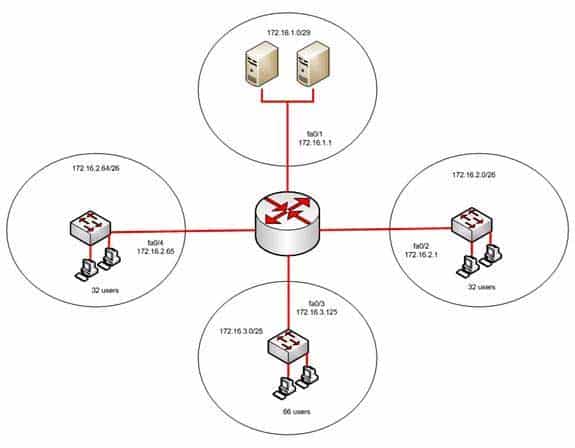
200-301 Part 14 Q13 135 Objective:
Network Fundamentals
Sub-Objective:
Configure, verify, and troubleshoot IPv4 addressing and subnetting -
What is the possible IP range that can be assigned to hosts on a subnet that includes the address 192.168.144.34/29?
- 192.168.144.32 – 192.168.144.63
- 192.168.144.33 – 192.168.144.38
- 192.168.144.33 – 192.168.144.48
- 192.168.144.28 – 192.168.144.40
Explanation:
Range 192.168.144.33 – 192.168.144.38 is the correct answer. To determine the range of addresses that can be assigned in a subnet, you must first determine the network ID of the subnetwork and the broadcast address of the subnetwork. All addresses that can be assigned to hosts will lie between these endpoints. The network ID can be obtained by determining the interval between subnet IDs. With a 29-bit mask, the decimal equivalent of the mask will be 255.255.255.248. The interval between subnets can be derived by subtracting the value of the last octet of the mask from 256. In this case, that operation would be 256 – 248 = 8. Therefore, the interval is 8.The first network ID will always be the classful network you started with (in this case 192.168.144.0). Each subnetwork ID will fall at 8-bit intervals as follows:
192.168.114.0
192.168.144.8
192.168.144.16
192.168.144.24
192.168.144.32
192.168.144.40We can stop at the 192.168.144.40 address because the address given in the scenario, 192.168.144.34, is in the network with a subnet ID of 192.168.144.32. Therefore, since the broadcast address for this network will be 1 less than the next subnet ID (192.168.144.39), the valid range of IP addresses is 192.168.144.33 – 192.168.144.38. 192.168.144.39 will be the broadcast address for the next subnet, and 192.168.144.40 will be the first valid address in the next subnet.
None of the other answers is the correct range.
Objective:
Network Fundamentals
Sub-Objective:
Apply troubleshooting methodologies to resolve problems -
Examine the output shown below:
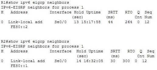
200-301 Part 14 Q15 136 What is true of this configuration?
- The link-local address of R1 is FE80::2
- The link-local address of R1 is FE80::1
- The area ID is 1
- No adjacency has formed
Explanation:
The output shows that the link-local address of R1 is FE80::1. R1’s link-local address appears in the output of R2 because the show ipv6 eigrp neighbors command displays information about the neighbor, not the local router.The link-local address of R1 is not FE80::2. That is the link-local address of R2.
Because the area ID is not displayed in the output, we do not know its value. The only 1 in the output is the value representing the process ID of both routers, IPv6-EIGRP neighbors for process 1.
It is not true that no adjacency has formed. There is an adjacency present; if there were not, the two routers would not appear in each other’s output of the show ipv6 eigrp neighbors command.
Objective:
Routing Fundamentals
Sub-Objective:
Configure, verify, and troubleshoot EIGRP for IPv6 (excluding authentication, filtering, manual summarization, redistribution, stub) -
DRAG DROP
Click and drag the network components and functions to their corresponding descriptions on the right.

200-301 Part 14 Q16 137 Question 
200-301 Part 14 Q16 137 Answer Explanation:
The following network components and functions should be matched to these corresponding descriptions:
– Transmission Control Protocol (TCP)/Internet Protocol (IP): TCP/IP is a suite of data communication protocols.
– Router: Separates broadcast domains while connecting different networks. Routers also provide a medium for connecting Local Area Network (LAN) and Wide Area Network segments.
– Layer 2 switching: Performed using a destination MAC address within a frame. In Layer 2 switching, switching is based on Media Access Control (MAC) addresses.
– Hierarchical model: Enables the designing of internetworks into layers. There are three layers in the hierarchical network design:
– Core layer: Provides high-speed data transfer between sites.
– Distribution layer: Includes LAN-based routers and Layer 3 switches and enables routing between Virtual Local Area Networks (VLANs).
– Access layer: Provides workgroup and end-user access, and is also referred to as the desktop layer.Objective:
Network Fundamentals
Sub-Objective:
Describe the impact of infrastructure components in an enterprise network -
Which of the following commands helps you determine the Layer 1 and Layer 2 up/down status of a Cisco interface?
- show controllers
- show running-config
- show interfaces trunk
- show interfaces
Explanation:
The show interfaces command displays the Layer 1 and Layer 2 operational status of an interface, along with other information.
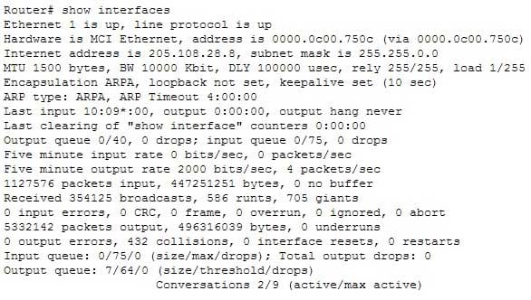
200-301 Part 14 Q17 138 Of interest in this output is the information contained on line 14 (also shown below). The figures for Runts and Giants (packets that are either too large or too small) indicate that collisions are occurring or that the NIC is malfunctioning:
Received 354125 broadcasts, 586 runts, 705 giants
As a part of troubleshooting this increase in collisions, you can also identify the speed of the interface by reading line 4, which says the bandwidth is 10000 Kbit, indicating a FastEthernet interface.
MTU 1500 bytes, BW 10000 Kbit, DLY 100000 usec, rely 255/255, load 1/255
You can also specify a particular interface for which information should be displayed, as shown below:
Router# show interfaces ethernet 0/0
Ethernet0/0 is administratively down, line protocol is down
Hardware is AmdP2, address is 0003.e39b.9220 (via 0003.e39b.9220)
Internet address is 10.1.0.254/16
MTU 1500 bytes, BW 10000 Kbit, DLY 1000 usec,
reliability 255/255, txload 1/255, rxload 1/255
Encapsulation ARPA, loopback not set
Keepalive set (10 sec)
ARP type: ARPA, ARP Timeout 04:00:00
<<output omitted>>
The sample output indicates that interface Ethernet 0/0 is in an administratively down, line protocol is down state. The first statement indicates the Layer 1 (Physical) status, while the second statement indicates the Layer 2 (Data Link) status of the interface. A status of administratively down always indicates that the interface is in a shutdown state; the interface can be activated by executing the command no shutdown. This command also indicates the configured bandwidth of the interface (10000 Kbit in this case).
The following lines of information concern the Physical layer:
Hardware is AmdP2, address is 0003.e39b.9220 (via 0003.e39b.9220)
Ethernet0/0 is administratively down, line protocol is downThis output indicates that the link has not been enabled. There are other combinations of up and down states that can indicate other conditions. For example, the following indicates the link is functioning:
Ethernet0/0 is up, line protocol is up
The output below indicates a problem at the other end of the link, perhaps meaning that the interface on the other end has not been enabled or that the port to which it is connected has been disabled.
Ethernet0/0 is up, line protocol is down (not connect)
The following lines of information concern the Data Link layer:
Encapsulation ARPA
line protocol is down
The show controllers command provides Layer 1 information only, including the type of cable detected (DTE/DCE) on a serial interface.
The show running-config command displays the current active configuration of the router, but does not indicate the operational status of its interfaces.
The show interfaces trunk command will not show the Layer 1 and Layer 2 up/down status of a Cisco interface. It will show all interfaces configured to be trunks. This command is very useful when you need to locate trunk interfaces on a switch with which you are not familiar. In the output of the command below, the three trunking interfaces are the Fa0/3, Fa0/9, and Fa0/12 interfaces.

200-301 Part 14 Q17 139 Objective:
LAN Switching Fundamentals
Sub-Objective:
Troubleshoot interface and cable issues (collisions, errors, duplex, speed) -
Which of the following are classless routing protocols? (Choose four.)
- Open Shortest Path First (OSPF)
- Enhanced Interior Gateway Routing Protocol (EIGRP)
- Interior Gateway Routing Protocol (IGRP)
- Routing Information Protocol version 1 (RIPv1)
- Border Gateway Protocol (BGP)
- Routing Information Protocol version 2 (RIPv2)
Explanation:
Open Shortest Path First (OSPF), Enhanced Interior Gateway Routing Protocol (EIGRP), Border Gateway Protocol (BGP), and Routing Information Protocol version 2 (RIPv2) are classless routing protocols.Intermediate-System-to-Intermediate System (IS-IS) is also a classless routing protocol.
The options IGRP and RIPv1 are incorrect because these are classful routing protocols.
The following are characteristics of classless routing protocols:
– The subnet mask is advertised with each route by using classless routing protocols.
– Flexible route summarization and supernetting (CIDR) are allowed in classless routing protocols.
– Classless routing protocols support variable length subnet masks (VLSM), which allow different subnets of a given IP network to be configured with different subnet masks.One of the main advantages of using a classless routing protocol is its ability to minimize the effects of discontiguous networks. When subnets of the same classful network are separated by another classful network, the networks are called discontiguous. Examine the diagram below:
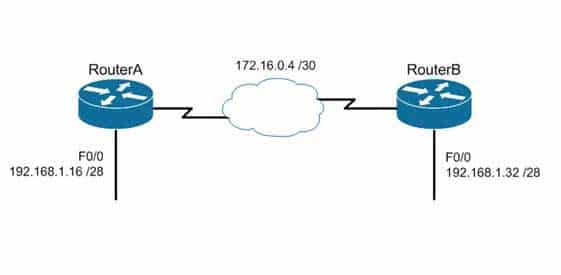
200-301 Part 14 Q18 140 The LAN networks extending from Router A and Router B are derived from the same Class C network, 192.168.1.0/24. A classful routing protocol such as RIP v1 would not be able to determine the direction to send the packets, but since classless protocols include the subnet mask in advertisements, they would not suffer the same problem. Whenever networks with non-default subnet masks are used, a classless routing protocol will be required.
Below are some examples of networks that do not have default masks. You can recognize them by the fact that they are not /8, /16, or /24.
192.168.10.0/27
10.5.6.0/22
172.68.0.0/18All of the classless protocols discussed here are interior routing protocols with the exception of Border Gateway Protocol (BGP), which is an external routing protocol used to connect different autonomous systems. For example, BGP would be used to connect two OSPF autonomous systems (AS).
Objective:
Routing Fundamentals
Sub-Objective:
Interpret the components of routing table -
You are configuring a serial link between a Cisco router and a router produced by another vendor. What would be the advantages of using Point to Point Protocol (PPP) over High Level Data Link Control (HDLC) in this scenario?
- HDLC has a proprietary “type” field that may be incompatible with equipment from other vendors.
- HDLC is not available on non-Cisco routers.
- PPP is faster.
- PPP performs error checking.
Explanation:
High Level Data Link Control (HDLC) has a proprietary “type” field that may be incompatible with equipment from other vendors. It is recommended that PPP always be used when combining equipment from multiple vendors because this Data Link layer WAN protocol is an industry standard. PPP is implemented in the same manner on all PPP-capable equipment.HDLC is available on non-Cisco routers. However, the Cisco implementation has a “type” field that may prevent the connection from working.
PPP is not faster than HDLC.
PPP performs error checking, but so does HDLC.
Objective:
WAN Technologies
Sub-Objective:
Describe WAN access connectivity options -
What Cisco IOS command produced the following as a part of its output?
Port Security: Enabled
Port status: SecureUp
Violation mode: Shutdown
Maximum MAC Addresses: 2
Total MAC Addresses: 2
Configured MAC Addresses: 2
Aging Time: 30 mins
Aging Type: Inactivity
SecureStatic address aging: Enabled
Security Violation count: 0
- show interfaces port-security
- show port-security interface
- show ip interface
- show interfaces switchport
Explanation:
The output is the result of executing the show port-security interface command. The sample output indicates that port security has been enabled on the interface, and that a maximum of two MAC addresses has been configured. A violation mode of Shutdown indicates that if a third MAC address attempts to make a connection, the switch port will be disabled. It is useful to note that you must specify a port number when you execute the command. In this case, the command was Switch# show port-security interface fastethernet0/1.The output was not produced by the show interfaces port-security command. This is not a valid Cisco command.
The output was not produced by the show ip interface command. It displays protocol-related information about an interface, and nothing pertaining to switch port security. An example of its output follows:
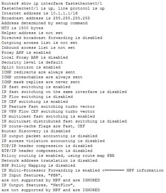
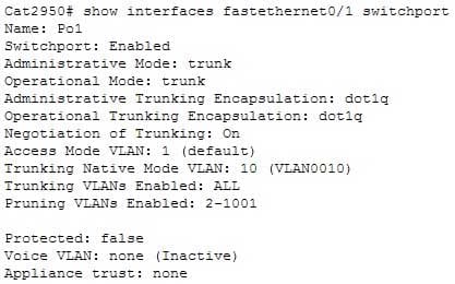
200-301 Part 14 Q20 141 The output was not produced by the show interfaces switchport command. This command displays non-security related switch port information, such as administrative and operational status and trunking:
200-301 Part 14 Q20 142 Objective:
Infrastructure Security
Sub-Objective:
Configure, verify, and troubleshoot port security