200-301 : Cisco Certified Network Associate (CCNA) : Part 19
-
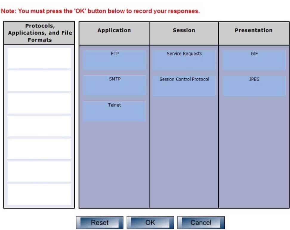
DRAG DROP
Click and drag the following protocols, applications, and file formats on the left, to their corresponding Open Systems Interconnection (OSI) layers.

200-301 Part 19 Q01 169 Question 
200-301 Part 19 Q01 169 Answer Explanation:
The application layer is responsible for interacting directly with the application. It provides application services such as e-mail and File Transfer Protocol (FTP), Simple Mail Transfer Protocol (SMTP) and telnet. Some of its associated protocols include:
– FTP: Used to transfer data between hosts through the Internet or a network.
– SMTP: SMTP is a Transmission Control Protocol (TCP)/Internet Protocol (IP) protocol which is used to send and receive e-mail messages.
– Telnet: Used to allow remote logins.The session layer is used to create, manage, and terminate sessions between communicating nodes. Some of the protocols and applications associated with this layer include:
– Service requests: Service requests and service responses which take place between different applications are handled by the session layer.
– Session Control Protocol (SCP): Allows a host to have multiple conversations with another host using the same TCP connection.The Presentation layer in the OSI model enables coding and conversion functions for application layer data. The formatting and encryption of data is done at this layer, as the Presentation layer converts data into a format which is acceptable by the application layer. Some of the file types associated with this layer include:
– Graphics Interchange Format (GIF)
– Joint Photographic Experts Group (JPEG)
– Tagged Image File Format (TIFF)Other layers in the OSI model include:
– Transport: Responsible for error free and sequential delivery of data. This layer is used to manage data transmission between devices, a process known as flow control. The Transport layer protocols are Transmission Control Protocol (TCP) and User Datagram Protocol (UDP).
– Physical: Consists of hardware for sending and receiving data on a carrier. The protocols which work at the Physical layer include Fast Ethernet, RS232, and Asynchronous Transfer Mode (ATM).
– Network: Used to define the network address or the Internet Protocol (IP) address which is then used by the routers to forward make forwarding decisions.
– Data Link: Ensures reliable transmission of data across a network on the basis of Layer 2 addresses such as MAC addresses (Ethernet) or DLCIs (Frame Relay).Objective:
Network Fundamentals
Sub-Objective:
Compare and contrast TCP and UDP protocols -
Which statement is true regarding Inter-Switch Link (ISL) frame tagging?
- ISL uses a native VLAN.
- ISL works with non-Cisco switches.
- ISL adds a 26-byte trailer and 4-byte header.
- The original Ethernet frame is not modified.
Explanation:
With ISL frame tagging, the original Ethernet frame is not modified. ISL encapsulates the original frame by adding a 26-byte header and a 4-byte Cyclic Redundancy Check (CRC) trailer. The original Ethernet frame is placed between the header and trailer. A normal Ethernet frame can have a maximum size of 1,518 bytes, and therefore adding the header and trailer size gives an ISL frame a maximum size of 1,548 bytes.ISL frame tagging does not use the concept of a native VLAN. Instead, Institute of Electrical and Electronics Engineers (IEEE) 802.1q frame tagging uses the native VLAN. Unlike ISL trunks, where every frame traversing the trunk is tagged with an ISL header and a trailer, 802.1Q trunks allow untagged frames over the native VLAN. An untagged frame does not carry VLAN identification information in it and is a simple Ethernet frame.
ISL is proprietary to Cisco, and thus does not work with non-Cisco switches.
ISL frame tagging does not add a 26-byte trailer and 4-byte header. It adds a 26-byte header and 4-byte trailer.
Objective:
LAN Switching Fundamentals
Sub-Objective:
Configure and verify Layer 2 protocols -
Which two statements are TRUE of Internet Protocol (IP) addressing? (Choose two.)
- Public addresses are registered with the Internet Assigned Numbers Authority (IANA).
- These addresses are publicly registered with the Internet Service Provider (ISP).
- Through a public IP address, you can access another computer on the Internet, such as a Web server.
- The ranges of public IP addressing are 10.0.0.0 to 10.255.255.255, 172.16.0.0 to 172.31.255.255, and 192.168.0.0 to 192.168.255.255.
- Private addresses are allocated by the Internet Assigned Numbers Authority (IANA).
Explanation:
Public addresses are publicly registered with the Internet Assigned Numbers Authority (IANA). Through a public IP address, you can access an Internet computer like a Web server.The following statements are true of public IP addressing:
– These addresses are publicly registered with the Internet Assigned Numbers Authority (IANA)
– Through a public IP address, you can access another Internet computer, such as a Web server.
– Other people on the Internet can obtain information about or access to your computer via a public IP address.
– Public IP addresses are visible to the public.The option stating that public IP addresses are publicly registered with the Internet Service Provider (ISP) is incorrect. Public IP addresses are registered with the Internet Assigned Numbers Authority (IANA). Since 1998, InterNIC has been primarily responsible for allocating domain names and IP addresses under the governance of the Internet Corporation for Assigned Names and Numbers (ICANN) body, a U.S. non-profit corporation that was created to oversee work performed by the Internet Assigned Numbers Authority (IANA).
The option stating that 10.0.0.0 to 10.255.255.255, 172.16.0.0 to 172.31.255.255, and 192.168.0.0 to 192.168.255.255 are the range of public IP addressing is incorrect. These ranges belong to private IP addressing.
The option stating that private addresses are allocated by the IANA is incorrect. Private IP address are not managed, but are used by private organizations as they see fit. The IANA is governed by ICANN, and its primarily role is to allocate overseas global IP addresses from the pools of unallocated addresses, as well as DNS root zone management.
Objective:
Network Fundamentals
Sub-Objective:
Describe the need for private IPv4 addressing -
You have two routers in your OSPF area 0. Router 1 is connected to Router 2 via its Serial 1 interface, and to your ISP via the Serial 0 interface. Router 1 is an ASBR.
After your assistant configures a default route on Router 1, you discover that whenever either router receives packets destined for networks that are not in the routing tables, it causes traffic loops between the two routers.
To troubleshoot, you execute the show run command on Router 1. Part of the output is shown below:
<output omitted>
IP route 0.0.0.0 0.0.0.0 serial 1
Router ospf 1
Network 192.168.5.0 0.0.0.255 area 0
Default-information originate
Which command or set of commands should you execute on Router 1 to stop the looping traffic while maintaining Router 2’s ability to send traffic to the Internet?
- Execute the no default-information originate command.
- Execute the no ip route 0.0.0.0 0.0.0.0 serial 1 command and then execute the ip route 0.0.0.0 0.0.0.0 serial 0 command.
- Execute the default-information originate always command.
- Execute the no network 192.168.5.0 area 0 command and then execute the network 192.168.5.0 255.255.255.0 area 0 command.
Explanation:
You should execute the no ip route 0.0.0.0 0.0.0.0 serial 1 command followed by the ip route 0.0.0.0 0.0.0.0 serial 0 command. The original configuration command was executed on the wrong interface on Router 1 by your assistant. It should be executed on Serial 0, which is the connection to the ISP. The show run command indicates that with the current configuration, if Router 2 receives a packet not in its table, it sends it to Router 1, and then Router 1 sends it back out on Serial 1. This redirects the packet back to Router 2, and the loop begins. By changing the configuration to Serial 0, Router 1 will start forwarding all traffic not in the routing table to the ISP.You should not execute the no default-information originate command. This command instructs Router 1 to NOT inject the default route into area 0, which is the desired behavior. Running this command would stop the loop, but would leave Router2 with no default route to send packets to the Internet.
You should not execute the default-information originate always command. The addition of the always parameter instructs Router 1 to inject a default route into area 0, even if one does not exist on Router 1. This is unnecessary, since Router 1 does have a default route configured, and will not change the existing looping behavior.
You should not execute the no network 192.168.5.0 area 0 command followed by the network 192.168.5.0 255.255.255.0 area 0 command. There is nothing wrong with the original network command. Also, the network 192.168.5.0 255.255.255.0 area 0 command uses an incorrect mask type. The mask must be in the wildcard format. Moreover, since it is incorrect, this will have the effect of disabling OSPF on the network connecting the two routers.
Objective:
Routing Fundamentals
Sub-Objective:
Configure, verify, and troubleshoot single area and multi-area OSPFv2 for IPv4 (excluding authentication, filtering, manual summarization, redistribution, stub, virtual-link, and LSAs) -
Which Cisco IOS command is used to provide a description to an interface?
- description
- interface-description
- interface description
- description interface number
Explanation:
The description command is used to provide a description to an interface. It is not a mandatory configuration. However, if you have configured the description for an interface, anyone who is working on the router can easily identify the purpose of the interface. Following is an example of the description command:RouterA(config)# interface s0 RouterA(config-if)# description AT&T T1 to Internet
All the other options are syntactically incorrect.
Objective:
Infrastructure Management
Sub-Objective:
Perform device maintenance -
What is the broadcast address for subnet 172.25.4.0/23?
- 172.25.4.255
- 172.25.5.255
- 172.25.6.255
- 172.25.7.255
Explanation:
The broadcast address for subnet 172.25.4.0/23 will be 172.25.5.255.When using a mask of /23, the subnet mask is 255.255.254.0. This means that the interval, or block size, of each subnet is 2, and that it will be incremented in the third octet. Therefore, the next network ID after 172.25.4.0 will be 172.25.6.0. Since the broadcast address of each subnet is the last address in that subnet before the next network ID, the broadcast address will be 172.25.5.255.
172.25.4.255 is a valid address in the 172.25.4.0/23 network, since the network range is 172.25.4.1 – 172.25.5.254.
172.25.6.255 is a valid address in the 172.25.6.0/23 network. Its range is 172.25.6.1 -172.25.7.254. Since the next network ID after 172.25.6.0 is 172.25.8.0, as the interval is 2 and it is incremented in the third octet, the broadcast address would be 172.25.7.255.
For the same reason, 172.25.6.255 is the broadcast address for the 172.25.6.0/24 network.
Objective:
Network Fundamentals
Sub-Objective:
Apply troubleshooting methodologies to resolve problems -
Which subnet is IP address 172.16.5.2 /23 a member of, and what is the broadcast address for that subnet?
- subnet: 172.16.4.0, broadcast: 172.16.5.255
- subnet: 172.16.5.0, broadcast: 172.16.5.255
- subnet: 172.16.2.0, broadcast: 172.16.5.255
- subnet: 172.16.0.0, broadcast: 172.16.7.255
Explanation:
The IP address 172.16.5.2 /23 is a member of subnet 172.16.4.0 and has the broadcast address of 172.16.5.255. The valid host range is between 172.16.4.1 and 172.16.5.254.Binary form of IP address 172.16.5.2 = 10101100.00010000.00000101.00000010
Binary conversion for /23 netmask = 11111111.11111111.11111110.00000000
Decimal conversion for /23 netmask = 255.255.254.0Calculations:
Perform the AND operation between the IP address and the netmask to obtain the subnet ID:
Address = 10101100.00010000.00000101.00000010
Netmask = 11111111.11111111.11111110.00000000
——————————————————————————-
Subnetwork ID = 10101100.00010000.00000100.00000000Convert the binary version of the network ID to dotted decimal format, 172.16.4.0.
To obtain the broadcast address, replace the last 9 host bits (32 – 23 = 9 bits) of the network address, which yields the following:
Binary form of broadcast address = 10101100.00011001.00000101.11111111
Decimal form of broadcast address = 172.16.5.255
200-301 Part 19 Q07 170 Objective:
Network Fundamentals
Sub-Objective:
Apply troubleshooting methodologies to resolve problems -
You just finished configuring VLAN Trunking Protocol (VTP) in a network containing five switches. One of the switches is not receiving VLAN information from the switch that is acting as the server.
Which of the following could NOT be a reason why the switch is not receiving the information?
- The VTP domain name on the switch may be misspelled
- The VTP password may be misspelled on the switch
- The configuration revision number may be out of sync
- The VTP version used on the switch may be different
Explanation:
The configuration revision number does not need to match on the switches. The configuration number cannot be directly configured, but is instead synchronized during VTP updates.For VTP to function correctly, all of the following conditions must be true:
– The VTP version must be the same on all switches in a VTP domain.
– The VTP password must be the same on all switches in a VTP domain.
– The VTP domain name must be the same on all switches in a VTP domain.Objective:
LAN Switching Fundamentals
Sub-Objective:
Configure, verify, and troubleshoot VLANs (normal/extended range) spanning multiple switches -
Which is the valid broadcast ID for the IP address 192.24.134.12 with a subnet mask of 255.255.255.128?
- 192.24.134.127
- 192.24.134.128
- 192.24.134.129
- 192.24.134.131
Explanation:
192.24.134.127 is the valid broadcast ID for the IP address 192.24.134.12 with a subnet mask of 255.255.255.128. The valid range for the IP address 192.24.134.12 with a subnet mask of 255.255.255.128 is 192.24.134.1 – 192.24.134.126. The subnet ID is 192.24.134.0.Subnetting allows you to split single and large subnets defined by Class A, B, and C IP addresses into multiple subnets with smaller IP address host ranges. Subnetting allows efficient use of IP addressing space, which has become a scarce resource.
To subnet an existing network, you will use host bits to split the IP address into multiple logical subnets. For example, if you use three bits of the host ID for subnetting, you have created 23 = 2 x 2 x 2 = 8 subnets. Remaining bits of the host ID in decimal form will form the number of hosts on each subnet.
All other options are incorrect as these IP addresses fall in other subnets.
192.24.134.128 is the network ID for the next subnet created when using a mask of 255.255.255.128 on the class C network 192.24.134.0. The following network IDs are created when you use a mask of 255.255.255.128 on the class C network 192.24.134.0:
– 192.24.134.0 – Valid range 192.24.134.1-192.24.134.126, 192.24.134.127 is the broadcast
– 192.24.134.128 – valid range 192.24.134.129-192.24.134.254, 192.24.134.255 is the broadcast192.24.134.129 and 192.24.134.131 are both valid addresses in the second subnet created, that is, the 192.24.128.0 network.
Objective:
Network Fundamentals
Sub-Objective:
Configure, verify, and troubleshoot IPv4 addressing and subnetting -
Which of the following commands will let you see the current operating mode for a switch port?
- show interface fastethernet0/1 detail
- show controllers fastethernet0/1
- show interface fastethernet0/1 status
- show interfaces fastethernet0/1 switchport
Explanation:
The show interfaces switchport command is used to verify the operational and configured status of a switch port. The output of the command is follows:switch# show interfaces fastethernet0/1 switchport
Name: Fa0/1
Switchport: Enabled
Administrative Mode: static access
Operational Mode: static access
Administrative Trunking Encapsulation: dot1q
Operational Trunking Encapsulation: dot1q
Negotiation of Trunking: Off
Access Mode VLAN: 1 (default)
Trunking Native Mode VLAN: 1 (default)
Voice VLAN: none
<<output omitted>>This output indicates that the operational mode of the port is “static access,” which means the port is currently operating as an access port.
The show controllers command is used to view hardware-related information on router and switch interfaces. It is useful for troubleshooting and diagnosing issues with interfaces. It does not display the operational status of the switch port.
The show interface fastethernet0/1 detail and show interface fastethernet0/1 status commands are incorrect because they are not valid Cisco IOS commands.
Objective:
Infrastructure Management
Sub-Objective:
Use Cisco IOS tools to troubleshoot and resolve problems -
Your network is configured as shown in the following exhibit. When you trace traffic sourced from R3 destined for a LAN network off of R2 (not shown in the diagram), you see the traffic is being forwarded from R1 to ISP1 rather than to R2.

200-301 Part 19 Q11 171 Which of the following issues could NOT be causing this behavior?
- The network command has not been executed on the interface leading to the LAN off R2
- The passive interface command has been issued on the Gi0/4 interface of R1
- A default route exists on R1 that leads to ISP1
- RIPv2 has not been enabled on R2
Explanation:
This issue would NOT be caused by executing the passive interface command on the Gi0/4 interface of R1. This command prevents the advertisement of RIP routes on that interface. If that command had been issued, the traffic would not be forwarded to R1 because R3 would not know about the route to the LAN off of R2. This command would also prevent R3 from knowing about the default route to ISP1. Since the traffic is being routed to ISP1, this command must not have been executed.All of the other options could potentially because traffic destined for R2 to be forwarded from R1 to ISP1, rather than to R2.
It is true that a default route exists on R1 that leads to ISP1. If this default route did not exist, the traffic destined for R2 would simply be dropped at R1 instead of being forwarded to ISP1.
If the network command has not been executed on the interface leading to the LAN off of R2, the network leading to the LAN off R2 would not advertised by R2. That would make R1 unaware of this destination. In that case, R1 would use the default route to send traffic destined for R2 to ISP1. We know such a default route must exist, or the traffic would simply be dropped at R1.
If RIPv2 has not been enabled on R2, R2 would not be receiving or advertising any RIP routes. When the packets destined for the network off of R2 arrive at R1, R1 will have not have a route to that network. In that case R1 will forward the traffic to ISP1 using the default route.
Objective:
Routing Fundamentals
Sub-Objective:
Configure, verify, and troubleshoot RIPv2 for IPv4 (excluding authentication, filtering, manual summarization, redistribution) -
You need to configure Network Address Translation (NAT) to allow users access to the Internet. There are 62 private hosts that need Internet access using the private network 10.4.3.64 /26, and all of them will be translated into the public IP address of the serial interface.
Which of the following NAT configurations will allow all 62 hosts to have simultaneous Internet access?
-
Router(config)# ip nat pool POOLNAME 10.4.3.64 /26

Router(config)# interface s0

Router(config-if)# ip nat inside source 1 pool POOLNAME overload
-
Router(config)# access-list 1 permit 10.4.3.64 0.0.0.127

Router(config)# interface s0/0

Router(config-if)# ip nat source list 1 pool POOLNAME overload
-
Router(config)# access-list 1 permit 10.4.3.64 /26

Router(config)# ip nat inside source list 1 interface serial 0
-
Router(config)# access-list 1 permit 10.4.3.64 0.0.0.63
Router(config)# ip nat inside source list 1 interface serial 0 overload
Explanation:
You should execute the following commands:Router(config)# access-list 1 permit 10.4.3.64 0.0.0.63 Router(config)# ip nat inside source list 1 interface serial 0 overload
A successful NAT configuration requires the creation of an access control list (ACL) to identify the private IP addresses that will be translated, as well as an ip nat inside source command to dictate what public IP addresses will be used for translation. Cisco uses the term “inside local” for IP addresses prior to translation, and “inside global” for public IP addresses after translation.
The access-list 1 permit 10.4.3.64 0.0.0.63 command correctly identifies the private host network of 10.4.3.64 /26, consisting of 62 hosts.
The ip nat command is broken down as follows:
– inside: indicates that packets received on the inside (private) interface will be translated
– list 1: specifies that access list 1 will be used to determine which private IP addresses will be translated
– interface serial 0: specifies that NAT will translate private IP addresses into the IP address of the serial 0 interface
– overload: allows NAT to reuse the IP address of the serial interface for all private IP addresses, providing them simultaneous access to the InternetThe correct wildcard mask is critical to ensuring that the access list allows translation of all LAN devices. For example, if the private LAN used the 192.168.9.0/24 network and 167 devices were present in the network, the correct wildcard mask would be 0.0.0.255. If you used an incorrect wildcard mask, such as 0.0.0.3, only the 192.168.9.0/30 network would be allowed translation (only the IP addresses 192.18.9.1 and 192.168.19.2.) Of the 167 devices, 165 would not receive translation.
The overload keyword is required in this configuration, since there are more private IP addresses (62) than there are public IP addresses (one). Overload activates NAT overloading, often called Port Address Translation (PAT), and assigns each private IP address a unique, dynamic source port in router memory to track connections. If the overload keyword were not included in the NAT configuration, only one private host could access the Internet at a time.
An alternate solution would involve the creation of a pool of public IP addresses on the NAT router, and applying the access control list to the NAT pool:
Router(config)# ip nat pool NATPOOL 201.52.4.17 201.52.4.22 netmask 255.255.255.248
Router(config)# ip nat inside source list 1 pool NATPOOL overload
The first command creates a NAT pool with six public IP addresses on subnet 201.52.4.16/29, which will be used for translation. The second command then ties access list 1 to the NAT pool, and specifies overload so that the six public addresses can be reused as often as necessary, allowing all of the private IP addresses simultaneous Internet access.
In both of these examples, dynamic mapping is used. Without dynamic mapping, it is not possible for computers from outside the network to establish a connection with computers inside the network unless a static mapping between the private IP address and the public IP address is established on the NAT device.
A common alternative approach is to use public IP addresses in the DMZ rather than private IP addresses, and to place any computers than must be accessed from outside the network in the DMZ. In this case, NAT is not required between the DMZ devices and the Internet. Even if public IP addresses are used in the DMZ, if the addresses undergo NAT translation, connections from outside the network will not be possible.
When NAT is used to translate a public IP address (or addresses) to private IP addresses, the NAT process is ONLY implemented on the router that connects the network to the Internet. This is because private IP addresses are not routable to the Internet, and translation must occur where the network connects to the Internet.
The following command sets are incorrect because they both involve the creation of a NAT pool:
Router(config)# ip nat pool POOLNAME 10.4.3.64 /26
Router(config)# interface s0
Router(config-if)# ip nat inside source 1 pool POOLNAME overload
and
Router(config)# access-list 1 permit 10.4.3.64 0.0.0.127
Router(config)# interface s0/0
Router(config-if)# ip nat source list 1 pool POOLNAME overload
The scenario states you must use the IP address of the serial interface as the public address. Also, the ip nat inside source command is configured in global configuration mode, not interface configuration mode. Finally, access control lists require inverse masks (such as 0.0.0.63). CIDR notation (as in POOLNAME 10.4.3.64 /26) is not allowed.
The following command set is incorrect because access control lists require inverse masks (such as 0.0.0.63) and CIDR notation (/26) is not allowed:
Router(config)# access-list 1 permit 10.4.3.64 /26
Router(config)# ip nat inside source list 1 interface serial 0
Also, the ip nat inside source command is configured in global configuration mode, not interface configuration mode.
Objective:
Infrastructure Services
Sub-Objective:
Configure, verify, and troubleshoot inside source NAT -
-
Which type of connector is used for an Integrated Services Digital Network Basic Rate Interface (ISDN BRI) connection?
- DB-60
- RJ-45
- AUI
- Console
Explanation:
An RJ-45 connector is used for an ISDN BRI connection. A BRI port is used in order to connect an asynchronous BRI interface.The DB-60 option is incorrect because the DB-60 connector is used to provide connectivity between synchronous serial interfaces and Cisco routers. The serial ports are used to connect with the synchronous serial interfaces. DB-60 serial ports are used for Wide Area Network (WAN) connections. High-speed lines (E1 or T1) can be configured using serial ports.
The AUI option is incorrect because the AUI connector is used with Ethernet ports.
The console option is incorrect because console port enables device management. It provides out-of-band access to the router command line interface.Objective:
WAN Technologies
Sub-Objective:
Describe WAN access connectivity options -
At which of the following layers of the Cisco three-tier architecture should port security be implemented?
- Access layer
- Distribution layer
- Core layer
- Edge layer
Explanation:
Port security is one of the functions that should be performed at the Access layer. Among other functions that are done at this layer are:
– PoE
– Link aggregation
– QoSPort security should not be performed at the Distribution layer. Among the functions that should be done at this layer are:
– Routing updates
– Route summaries
– VLAN traffic
– Address aggregationPort security should not be performed at the Core layer. Among the functions that should be done at this layer are:
– Access-list checking
– Data encryption
– Address translationEdge is not one of the three layers in the Cisco three-tier model.
Objective:
Network Fundamentals
Sub-Objective:
Compare and contrast collapsed core and three-tier architectures -
You are the network administrator for your company. You are in the process of verifying the configuration of the network devices to ensure smooth network connectivity. You want information on the routes taken by packets so that you are able to identify the network points where packets are getting dropped.
Which Cisco IOS command should you use to accomplish this task in the most efficient manner?
- tracert
- traceroute
- extended ping
- ping
Explanation:
You should use the traceroute command. The traceroute command finds the path a packet takes while being transmitted to a remote destination. It is also used to track down routing loops or errors in a network. The following code is a sample output of the traceroute command:

200-301 Part 19 Q15 172 The tracert command is incorrect because this command is used by Microsoft Windows operating systems, not the Cisco IOS command line interface. However, the purpose of the tracert command is similar to the Cisco traceroute utility, namely to test the connectivity or “reachability” of a network device or host. The tracert command uses Internet Control Message Protocol (ICMP).
The extended ping Cisco IOS command can be issued on a router to test connectivity between two remote routers. This option is incorrect because you are not testing connectivity in this scenario; you want to determine the route a packet takes through the internetwork.
The ping command is also incorrect because you are not testing connectivity in this scenario; you want to determine the route a packet takes through the internetwork.
Objective:
Routing Fundamentals
Sub-Objective:
Configure, verify, and troubleshoot IPv4 and IPv6 static routing -
The router interfaces for a network are configured as shown in the following exhibit. (Click the Exhibit(s) button.)

200-301 Part 19 Q16 173 Warehouse 1 is having trouble connecting to the Internet. After troubleshooting the issue, several other connectivity issues are discovered.
What should you do to fix this problem?
- Change the IP address of the Warehouse 1 LAN interface.
- Change the IP address of the Warehouse 1 WAN interface.
- Change the IP address of the Main Office LAN Interface.
- Change the IP address of the Main Office WAN interface.
- Change the IP address of the Main Office Internet interface.
Explanation:
You should change the IP address of the Main Office WAN interface.With a 29-bit mask and the chosen class B address, the following network IDs are created:
172.16.0.0
172.16.0.8
172.16.0.16
172.16.0.24
172.16.0.32
172.16.0.40
172.16.0.48
172.16.0.56
172.16.0.64
…and so on, incrementing each time by 8 in the last octet. At the end of this series of increments, the network IDs will be:172.16.1.240
172.16.1.248
172.16.2.0172.16.1.248/29 is the subnet number for the WAN. This address cannot be used as a host address on the network. The legitimate addresses in this range are 172.16.0.249 through 172.16.0.254. This misconfiguration would cause both the Warehouse 1 and Warehouse 2 segment to have trouble connecting to the Internet.
All of the other addresses in the diagram are correct. The correct configuration of the network is shown in the following diagram:
200-301 Part 19 Q16 174 Objective:
Network Fundamentals
Sub-Objective:
Configure, verify, and troubleshoot IPv4 addressing and subnetting -
At which layer in the Open Systems Interconnection (OSI) model does flow control generally operate?
- the Network layer
- the Transport layer
- the Physical layer
- the Session layer
Explanation:
Flow control generally operates at the Transport layer of the OSI model. The Transport layer is responsible for the error-free and sequential delivery of data. This layer is used to manage data transmission between devices, a process known as flow control. The Transport layer protocols are Transmission Control Protocol (TCP) and User Datagram Protocol (UDP).Flow control does not operate at the Network layer in the OSI model. The Network layer defines the network address or the Internet Protocol (IP) address, which is then used by the routers to forward the packets.
Flow control does not operate at the Physical layer in the OSI model. The Physical layer describes the physical medium (i.e. Ethernet, fiber optic, or wireless) used for sending and receiving data on a carrier.
Flow control does not operate at the Session layer in the OSI model. The Session layer provides the mechanism for opening, closing and managing a session between end-user application processes.
Objective:
Network Fundamentals
Sub-Objective:
Compare and contrast OSI and TCP/IP models -
You have successfully configured a router, but it prompts you to run Setup mode every time the router is restarted. Based on the following output, what could be causing this problem?

200-301 Part 19 Q18 175 - The router does not have sufficient flash memory.
- The configuration register is incorrect.
- The configuration file could not be found in NVRAM.
- The router could not locate a configuration file over the network.
Explanation:
The configuration register is incorrect. The configuration register value of 2142 is preventing the router from loading the configuration file from NVRAM.The router configuration register is used to control various aspects of the router boot sequence, and defaults to a value of 2102. A configuration register of 2102 indicates that the router should boot normally, which consists of loading the Internetwork Operating System (IOS) into RAM, then loading the saved configuration file from Non-Volatile RAM (NVRAM) to configure the router.
Changing the configuration register to 2142 tells the router to bypass the saved configuration in NVRAM. This causes the router to boot with a default running configuration, and prompt to run the Initial Configuration Dialog (or Setup mode). Changing the configuration register to 2142 is necessary to perform password recovery or to bypass any other aspect of a saved configuration that might be causing problems. After the situation is resolved, the configuration register would then be changed back to the default of 2102 with the following command:
Router(config)# config-register 0x2102
The router is successfully loading the IOS from flash memory, so insufficient flash memory is an incorrect answer.
The configuration register is instructing the router to bypass the configuration file in NVRAM, so it is incorrect to state that the configuration file could not be found in NVRAM.
The configuration register is instructing the router to bypass the configuration file in NVRAM, so it is incorrect to state that the router could not locate a configuration file over the network.
Objective:
Infrastructure Management
Sub-Objective:
Use Cisco IOS tools to troubleshoot and resolve problems -
Which of the following is NOT a packet type used by Enhanced Interior Gateway Routing Protocol (EIGRP)?
- Query
- Reply
- Reply
- Response
Explanation:
Response is not a packet type used by EIGRP. The following are the packet types used by EIGRP:
– Hello/Ack: Establish neighbor relationships. The Ack packet is used to provide acknowledgement of a reliable packet.
– Update: Send routing updates.
– Query: Ask neighbors about routing information.
– Reply: Provide response to queries about routing information.
– Requests: Gain specific information from one or more neighbors.Objective:
Routing Fundamentals
Sub-Objective:
Configure, verify, and troubleshoot EIGRP for IPv4 (excluding authentication, filtering, manual summarization, redistribution, stub) -
Which of the following technologies allows a switch port to immediately transition to a forwarding state?
- Rapid STP
- PortFast
- VTP
- CDP
Explanation:
PortFast is a technology that allows a switch port connected to an end node such as a workstation, server, or printer to bypass the normal Spanning Tree Protocol (STP) convergence process. When a new device is powered up on a switch port, it will immediately transition to a forwarding state.NOTE: PortFast should only be used on access ports. It should not be used on trunk ports or on ports that connect to hubs, routers and other switches.
Rapid STP (RSTP) is a new STP standard that provides faster convergence than the original 802.1d STP. RSTP supports PortFast, but it must be configured explicitly.
The VLAN Trunking Protocol (VTP) does not allow for immediate transition to a forwarding state. VTP is used to synchronize VLAN databases between switches, and has no effect on STP.
The Cisco Discovery Protocol (CDP) does not allow for immediate transition to a forwarding state. CDP is used to verify connectivity and document directly connected Cisco devices. CDP is not related to STP.
Objective:
LAN Switching Fundamentals
Sub-Objective:
Configure, verify, and troubleshoot STP-related optional features