200-301 : Cisco Certified Network Associate (CCNA) : Part 23
-
Which of the following commands would allow you to determine the bandwidth of an interface?
- show interfaces
- show interfaces accounting
- show cdp
- show cdp neighbors
Explanation:
The show interfaces command shows information about each interface including a section on the bandwidth of the connection. If you wanted to locate this information in the output, it would be in the third down line as follows:MTU 1500 bytes, BW 10000 Kbit, DLY 100000 usec, rely 255/255, load 1/255 Where BW = bandwidth
The show interfaces accounting command focuses on the relative amounts of traffic going through each interface, but does not indicate the bandwidth.
The show cdp command shows information about the Cisco Discovery protocol, a Layer 2 protocol used by Cisco devices to advertise their existence and capabilities to other Cisco devices ion the network.
The show cdp neighbors command shows information about each discovered neighbor, but does not display the bandwidth of an interface.
Objective:
LAN Switching Fundamentals
Sub-Objective:
Troubleshoot interface and cable issues (collisions, errors, duplex, speed) -
What is the significance of the 1 in the following configuration?
router(config)# router eigrp 1
- It is the process ID for EIGRP and is locally significant to this router.
- It is the process ID for EIGRP and must be the same on all EIGRP routers.
- It is the AS number for EIGRP and is locally significant to this router.
- It is the AS number for EIGRP and must be the same on all EIGRP routers.
Explanation:
Enhanced Interior Gateway Routing Protocol (EIGRP) configuration requires the specification of an Autonomous System (AS) number with the router eigrp command. Any number can be chosen, but it must match on all EIGRP routers in the domain. This value may appear to be is similar to one used in enabling OSPF, which demands a process ID number but that value is locally significant to each router and need not match on each router.The syntax of this command is router eigrp [autonomous-system]. Therefore, the 1 in the example indicates an Autonomous System (AS) number, not a process ID.
The Autonomous System (AS) number is not locally significant to each router, and must match on all EIGRP routers.
Objective:
Routing Fundamentals
Sub-Objective:
Configure, verify, and troubleshoot EIGRP for IPv4 (excluding authentication, filtering, manual summarization, redistribution, stub) -
Based on the output of the show mac-address-table command shown below, where will the switch that produced this output send a frame with a destination MAC address of ffff.ffff.ffff?
Vlan Mac address Type Ports
<output omitted>
1 000f.e544.c2b3 dynamic Fa0/10
1 000d.4589.00b8 dynamic Fa0/5
1 00bd.000b.005bb dynamic Fa0/8
1 0001.0d44.bbdb dynamic Fa0/12
1 0014.0bd4.0054 dynamic Fa0/15
1 00bb.224b.0ac5 dynamic Fa0/1
- to all ports, listed and unlisted, except the originating port
- to Fa0/10, Fa0/5, Fa0/8, Fa0/12, Fa0/15, and Fa0/1
- to no ports, since the MAC address isn’t in the table
- to no ports, since the MAC address isn’t in the table
- to port Fa0/15
Explanation:
The MAC address ffff.ffff.ffff is called the Layer 2 broadcast address. It will be sent to all ports listed in the table, or known to the switch, as well as to all those unlisted, or not yet known by the switch. This excludes the originating port only.It will not send the frame only to the ports listed in the table (Fa0/10, Fa0/5, Fa0/8, Fa0/12, Fa0/15, and Fa0/1). It will also be sent to ports that are as yet unknown by the switch.
It will not prevent the frame from being sent to any ports because the MAC address is not listed. Broadcast addresses are not listed in the MAC address table. These addresses are only used to send to all hosts.
It will not send the frame to all ports except the ports listed. This would be the switch’s behavior if the address of the frame in question was not a broadcast address and was not listed in the MAC address table. Until a switch knows where a frame goes, it will send the frame to all ports that are still unknown or unlisted, with the exception of the port on which it arrived.
It will not send the frame to port Fa0/15 only. If the frame were addressed to 0014.0bd4.0054, the switch would forward the frame to that port only. When a switch receives a unicast frame with a destination MAC address that is listed in the table, it will only send the frame to that port.
Objective:
LAN Switching Fundamentals
Sub-Objective:
Describe and verify switching concepts -
You need to set the Telnet password to “john” on a Cisco router. Which set of commands would you use?
-
Router(config)#line vty 0 4 Router(config-line)#login Router(config-line)#password john -
Router(config)#line con 0

Router(config-line)#login

Router(config-line)#password john
-
Router(config)#line vty 0 4

Router(config-line)#login

Router(config-line)#enable secret john
-
Router(config)#line con 0

Router(config-line)#login

Router(config-line)#enable password john
Explanation:
The set of commands which would be used to configure the Telnet password to “john” on a Cisco router is:Router(config)#line vty 0 4 Router(config-line)#login Router(config-line)#password john
The line vty command is used to configure the router to enable Telnet access. By using this command, the router can be configured to accept one or more Telnet sessions.
The login and password parameters are the line configuration commands used to configure the password. The password command specifies the password and the login command instructs the router to require the password. By default, the login parameter is present in the configuration of the VTY lines. Because its presence indicates that a password is required for connecting to the VTY lines, if a password has not been configured on the VTY lines, a connection cannot be made. If an attempt were made to connect to the VTY line with the login parameter in effect and no password present, the following error message would be generated:
Router2# telnet 10.3.1.1
Trying 10.3.1.1Open

Password Required, but none set
[Connection to 10.3.1.1 closed by foreign host]
Router2#
The following set of commands would be used to configure the console password on a Cisco router, and so it is incorrect for this scenario.
Router(config)# line con 0
Router(config-line)# login
Router(config-line)# password john
The commands enable secret john and enable password john would be used to configure the enable secret password and the enable password for the router. However, they cannot be used to configure the Telnet password. Therefore, these options are incorrect.
Objective:
Infrastructure Management
Sub-Objective:
Configure and verify device management -
-
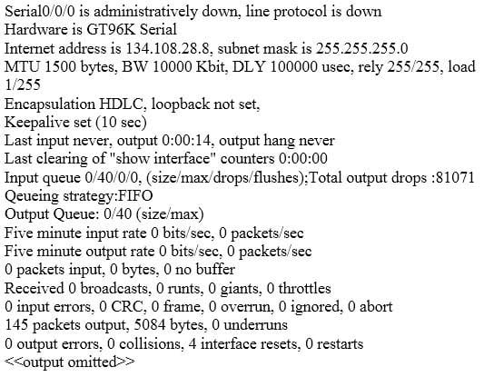
Which Cisco IOS command would produce the following output?
200-301 Part 23 Q04 201 - show ip interface
- show ip interface brief
- show interfaces
- show interface brief
Explanation:
The output given in the question is produced with the show interfaces command. This command is used to view the statistics for the configured interfaces on the router. From the sample output, we can determine the following facts:
The interface has not been enabled, as indicated by the first line Serial0/0/0 is administratively down. It is not ready to for to forward packets. To enable it, the no shutdown command should be entered.
– Line 3 shows that the subnet mask is 255.255.255.0.
– Line 3 shows that the IP address is 134.108.28.8, a public IP address.
– Line 6 shows that the encapsulation is HDLC, which is the default.
– The interface is NOT connected to a LAN, because it is a serial interface.Two fields worth mentioning in the output of the show interfaces command are the no buffer and the ignored fields. The ignored field shows the number of received packets ignored by the interface because the interface hardware ran low on internal buffers. The no buffer field shows the number of received packets discarded because there was no buffer space in the main system. When either of these two counters begins to increment, it could be the result of a broadcast storm.
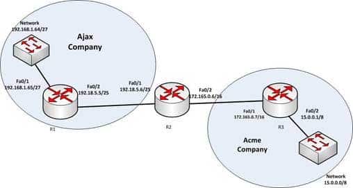
Since the show interfaces command displays the up/down state of the interfaces, it is a good command for troubleshooting. For example, any time users cannot access a resource that requires them to traverse a router, it is always a good idea to use show interfaces to take a quick look at the state of the interfaces. In the example diagram below, users cannot access the resource in the network of the Acme Company from the LAN in the Ajax Company. The first step would be to execute the show interfaces command in R1 to verify functionality of the interfaces on R1.
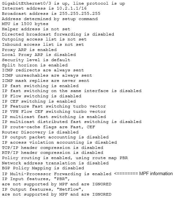
200-301 Part 23 Q05 202 The show ip interface command is incorrect because this command is used to view whether the interfaces configured for Internet Protocol (IP) are usable. Following is a sample output of the show ip interface command:
200-301 Part 23 Q05 203 The show ip interface brief command is incorrect because this command provides an overview of all the interfaces configured for IP on the router. The following is sample output from the show ip interface brief command. It can be quite useful for troubleshooting as well. For example, if you cannot ping the Ethernet1 interface from a host on the Ethernet 0 LAN, you could determine from the output below that the Ethernet 1 interface is administratively down.
Router# show ip interface brief

Interface IP-Address OK? Method Status Protocol
Ethernet0 12.17.10.5 YES NVRAM up up
Ethernet1 unassigned YES unset administratively down down
Loopback0 12.17.20.5 YES NVRAM up up
Serial0 12.17.30.5 YES NVRAM up up
The solution here would be to enter configuration mode for the interface Ethernet 1 and enable it with the no shutdown command.
The show interface brief command is incorrect because this command is not a valid Cisco IOS command.
Objective:
LAN Switching Fundamentals
Sub-Objective:
Troubleshoot interface and cable issues (collisions, errors, duplex, speed) -
You are a network administrator for your organization. Your organization has two Virtual LANs (VLANs) named Marketing and Production. All switches in the network have both VLANs configured on them. Switches A, C, F, and G have user machines connected for both VLANs, while switches B, D, and E have user machines connected for the Production VLAN only. (Click the Exhibit(s) button to view the network diagram.)
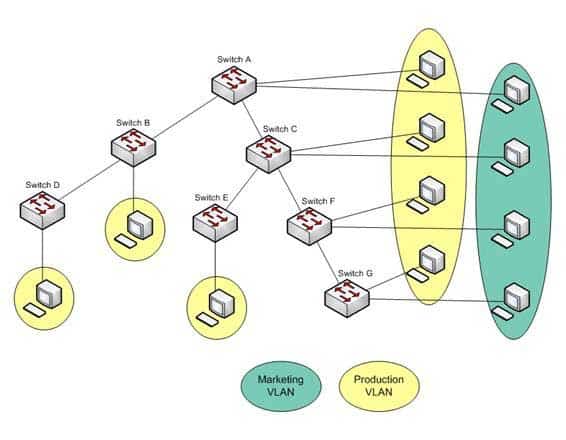
200-301 Part 23 Q06 204 To reduce broadcast traffic on the network, you want to ensure that broadcasts from the Marketing VLAN are flooded only to those switches that have Marketing VLAN users.
Which Cisco switch feature should you use to achieve the objective?
- PVST
- RSTP
- VTP Pruning
- Dynamic VLANs
Explanation:
The VLAN Trunking Protocol (VTP) pruning feature of Cisco VTP allows switches to dynamically delete or add VLANs to a trunk. It restricts unnecessary traffic, such as broadcasts, to only those switches that have user machines connected for a particular VLAN. It is not required to flood a frame to a neighboring switch if that switch does not have any active ports in the source VLAN. A trunk can also be manually configured with its allowed VLANs, as an alternative to VTP pruning.All other options are incorrect because none of these features can be used to achieve the objective in this scenario.
The Per-VLAN Spanning Tree (PVST) feature allows a separate instance of Spanning Tree Protocol (STP) per VLAN. Each VLAN will have its own root switch and, within each VLAN, STP will run and remove loops for that particular VLAN.
Rapid Spanning Tree Protocol (RSTP) is an Institute of Electrical and Electronics Engineers (IEEE) standard. It reduces high convergence time that was previously required in STP implementations. It is interoperable with STP (802.1d).
With dynamic VLANs, the switch automatically assigns a switch port to a VLAN using information from the user machine, such as its Media Access Control (MAC) address or IP address. The switch then verifies information with a VLAN Membership Policy Server (VMPS) that contains a mapping of user machine information to VLANs.
Objective:
LAN Switching Fundamentals
Sub-Objective:
Configure, verify, and troubleshoot VLANs (normal/extended range) spanning multiple switches -
You are the switch administrator for InterConn. The network is physically wired as shown in the diagram. You are planning the configuration of STP. The majority of network traffic runs between the hosts and servers within each VLAN.
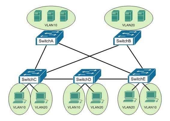
200-301 Part 23 Q07 205 You would like to designate the root bridges for VLANS 10 and 20. Which switches should you designate as the root bridges?
- Switch A for VLAN 10 and Switch E for VLAN 20
- Switch A for VLAN 10 and Switch B for VLAN 20
- Switch A for VLAN 10 and Switch C for VLAN 20
- Switch D for VLAN 10 and Switch B for VLAN 20
- Switch E for VLAN 10 and Switch A for VLAN 20
- Switch B for VLAN 10 and Switch E for VLAN 20
Explanation:
You should designate Switch A for VLAN 10 and Switch B for VLAN 20. The STP root bridge for a particular VLAN should be placed as close as possible to the center of the VLAN. If the majority of network traffic is between the hosts and servers within each VLAN, and the servers are grouped into a server farm, then the switch that all hosts will be sending their data to is the ideal choice for the STP root. Cisco’s default implementation of STP is called Per-VLAN Spanning Tree (or PVST), which allows individual tuning of the spanning tree within each VLAN. Switch A can be configured as the root bridge for VLAN 10, and Switch B can be configured as the root bridge for VLAN 20, resulting in optimized traffic flow for both.None of the other switches is in the traffic flow of all data headed towards the VLAN 20 or VLAN 10 server farms, so they would not be good choices for the root bridge for either VLAN. Care should be taken when adding any switch to the network. The addition of an older, slower switch could cause inefficient data paths if the old switch should become the root bridge.
Objective:
LAN Switching Fundamentals
Sub-Objective:
Configure, verify, and troubleshoot STP protocols -
Which command is used on the Cisco Catalyst 2950 series switch to configure a port as a VLAN trunk port?
- switchport mode trunk
- set trunk on
- switchport trunk on
- trunk mode on
Explanation:
The switchport mode trunk command is used on the Cisco Catalyst 2950 switch to configure a port as a VLAN trunk port. The syntax of the command is as follows:Switch(config-if)# switchport mode trunk
Trunk links are required between devices in any situation where traffic from multiple VLANs will traverse the link. This is also true when using VTP on the switches and in that case, even if inter-VLAN routing is not required. For example, if two switches in a VTP domain are connected together via an access link with no router present, then when you create a new VLAN on one of the switches, it will NOT be learned by the other switch.
When you configure a trunk link, there are two choices for encapsulation: 802.1q, which is the industry standard, and ISL, which is Cisco proprietary and will only work when both ends are Cisco equipment. Both protocols perform a crucial role in inter-VLAN routing by tagging packets with the VLAN to which the packets belong.
The following commands should be issued to configure FastEthernet 0/1 to function as a VLAN trunk port and use 802.1q encapsulation:
Switch# configure terminal
Switch(config)# interface fastethernet 0/1
Switch(config-if)# switchport mode trunk
Switch(config-if)# switchport trunk encapsulation dot1q
When configuring a trunk link between a switch and switch, the above commands would be used in both switches. However, when a trunk link is configured between a router and a switch, the process is different on the router. On the router end, you must do the following:
1. Enable the physical interface hosting the trunk link.
2. Ensure that no IP address exists on the physical interface.
3. Create a subinterface for each VLAN on the physical interface.
4. Set the trunking protocol on each subinterface.
5. Configure an IP address on each subinterface.The command set that would create a subinterface for VLAN 10, set the trunking protocol for the subinterface, and assign the subinterface an IP address is:
Router(config)#interface fastethernet 0/0
Router(config)#no ip address
Router(config-if)#no shutdown
Router(config)-if)exit
Router(config)#interface fastethernet 0/0.1
Router(config-if)#encapsulation dot1q 10
Router(config-if)#ip address 192.168.5.1 255.255.255.0
The set trunk on, switchport trunk on , and trunk mode on commands are incorrect because these are not valid Cisco IOS commands.
Objective:
LAN Switching Fundamentals
Sub-Objective:
Configure, verify, and troubleshoot VLANs (normal/extended range) spanning multiple switches -
You are considering a candidate for a job as a Cisco network technician. As part of the assessment process, you ask the candidate to write down the commands required to configure a serial interface, in the proper order with the correct command prompts. The candidate submits the set of commands shown below (line numbers are for reference only):
1 Router# configure terminal
2 Router(config)# interface S0
3 Router(config)# ip address 192.168.5.5
4 Router(config-if)# enable interface
5 Router(config-if)# description T1 to Raleigh
What part(s) of this submission are incorrect? (Choose all that apply.)
- The prompt is incorrect on line 1
- The IP address is missing a subnet mask
- The prompt is incorrect on line 5
- The prompt is incorrect on line 3
- The command on line 4 is incorrect
- The prompt is incorrect on line 4
- The description command must be executed before the interface is enabled
Explanation:
The IP address is missing a subnet mask, the prompt is incorrect on line 3, and the command enabling the interface (line 4) is incorrect.The correct prompts and commands are as follows:
Router# configure terminal
Router(config)# interface S0
Router(config-if)# ip address 192.168.5.5 255.255.255.0
Router(config-if)# no shutdown
Router(config-if)# description T1 to Raleigh
The prompt for line 3 would be Router(config-if)# because the interface S0 command was issued immediately prior to the ip address 192.168.5.5 command. The prompt will remain Router(config-if)# for lines 3, 4, and 5 as each command that applies to the S0 interface is executed, including the description command.
The command to enable the interface is no shutdown, not enable interface. Therefore, the command executed on line 4 was incorrect.
Objective:
Network Fundamentals
Sub-Objective:
Apply troubleshooting methodologies to resolve problems -
DRAG DROP
Click and drag the components on the left to their appropriate descriptions on the right.

200-301 Part 23 Q10 206 Question 
200-301 Part 23 Q10 206 Answer Explanation:
The following are the components used for network and Internet communications and their appropriate descriptions:
– Router: Separates broadcast domains while connecting different networks. Routers provide a medium for connecting Local Area Network (LAN) and Wide Area Networks (WAN) segments
– Hub: Provides a common connection point for the network devices. Hubs are generally used for LAN segmentation. A hub also regenerates the signal when it passes through its ports. Hub works at Layer 1 of the Open system Interconnection (OSI) model.
– Switch: Used to provide a separate connection for each node in a company’s internal network. Switches work at Layer 2 in the OSI model and perform the function of separating collision domains.
– Firewall: Used to secure the network against unauthorized and malicious access attempts.Objective:
Network Fundamentals
Sub-Objective:
Describe the impact of infrastructure components in an enterprise network -
You have discovered that Router 8 on your network is not receiving updates from Router 10. Router10 has an IP address of 201.56.41.9. All routers run RIP. Since you are new and not completely familiar with the topology of the network, you execute the debug ip rip command on Router 8 and receive the results shown below:
Router8# debug ip rip
*Mar 1 07:35:12.070: RIP: sending v2 update to 201.56.41.9 via Serial0/0 (201.56.41.88)
*Mar 1 07:35:12.074: RIP: build update entries
*Mar 1 07:35:19.638: RIP: ignored v2 packet from 201.56.41.9 (invalid authentication)
What can be the problem? (Choose all that apply.)
- Router 10 has not yet been configured for authentication
- Router 10 is configured for RIPv2 and Router 8 is configured for RIP v1.
- There is a connectivity problem between the routers.
- Router 10 is over 16 hops away
- The password is not correct.
Explanation:
The problem can be that Router 10 has not yet been configured for authentication or that the password is not correct. This can be ascertained by the line in the debug output shown below:*Mar 1 07:35:19.638: RIP: ignored v2 packet from 201.56.41.9 (invalid authentication)
It is not a problem with RIP version mismatch. If that were the problem, the following statement would be a line in the output:
*Mar 1 07:35:19.638: RIP: ignored v2 packet from 201.56.41.9 (illegal version)
It is not a connectivity problem. If there were a connectivity problem, we would not be receiving an attempt at an update from Router 10.
Router 10 is not more than 16 hops away. If that were the case, that information would be received from another router in its updates as shown below:
*Mar 1 07:35:19.638: RIP: received update from 201.56.41.10 via Serial0/0
201.56.41.9 in 16 hops (inaccessible)Objective:
Routing Fundamentals
Sub-Objective:
Configure, verify, and troubleshoot RIPv2 for IPv4 (excluding authentication, filtering, manual summarization, redistribution) -
What command produced the following output?
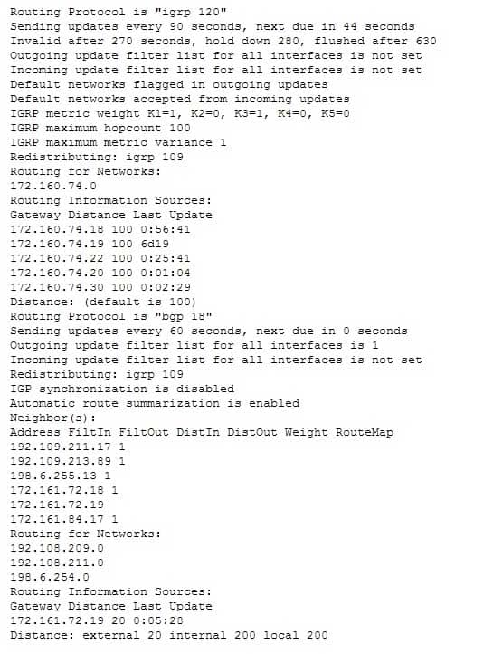
200-301 Part 23 Q12 207 - show ip process
- show ip route
- show ip route
- show ip routing process
Explanation:
The show ip protocols command is used to view the current state of active routing protocols. This command is issued from Privileged EXEC mode. It has the following syntax:Router# show ip protocols
This command does not have any parameters.
The output was not produced by the command show ip process or the show ip routing process. The show ip routing process and show ip process commands are incorrect because these are not valid Cisco IOS commands.
The output was not produced by the command show ip route. The show ip route command is is used to view the current state of the routing table. An example of the output is shown below.
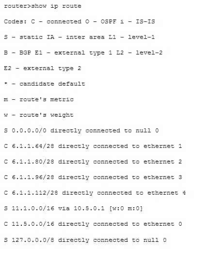
200-301 Part 23 Q12 208 Objective:
Routing Fundamentals
Sub-Objective:
Compare and contrast distance vector and link-state routing protocols -
Which of the following statements are NOT part of the guidelines for configuring VLAN Trunking Protocol (VTP) to ensure that VLAN information is distributed to all Cisco switches in the network? (Choose all that apply.)
- The VTP version must be the same on all switches in a VTP domain.
- The configuration revision number must be configured identically on all switches in a VTP domain.
- The VTP password must be the same on all switches in a VTP domain.
- The VTP domain name must be the same on all switches in a VTP domain.
- VLANs configured on clients should exist on the server switch.
- The switch(s) that will share VLAN information is(are) operating in VTP server mode
- The switches must be configured to use the same method of VLAN tagging
- The switches must be connected with trunk links
Explanation:
For all switches in a VTP domain, the VTP version, VTP password, and VTP domain name must be the same. Moreover, switches that will share VLAN information must be operating in VTP server mode, must be using the same VLAN tagging method (either 802.1q or ISL), and must be connected with trunk links.Many of these settings can be verified by using the show vtp status command. By viewing the output of the command on two switches that are not sharing information, inconsistencies that prevent the sharing of VLAN information can be identified. Consider the output from the two switches below:
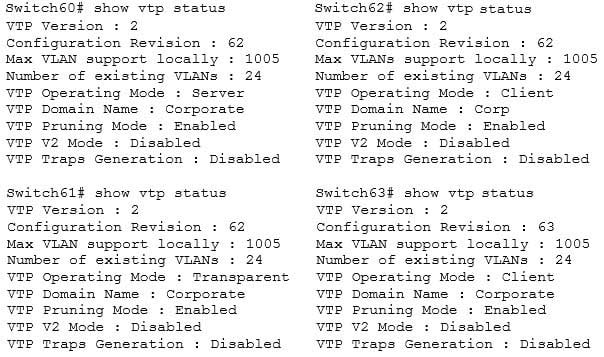
200-301 Part 23 Q13 209 Based on the output for the four switches, you should NOT expect Switch62 to exchange VLAN information with the other switches because the VTP domain names do not match. Line 6 shows that Swicth62 is set to Corp and the others are set to Corporate. The command to set the VTP domain name is:
Switch62(config)#vtp domain corporate
Switch62 is operating in Client mode, which means it will accept VLAN changes sent by switches operating in Server mode once the domain name mismatch is corrected. It will both process them and forward them, but will not allow VLAN changes to be made locally, and it will not save any of the VLAN information in NVRAM (line 5). The command to place a switch into Client mode is:
Switch62(config)#vtp mode client
Switch60 is operating in Server mode and will allow changes to be made locally, will send those changes to other switches, and WILL save all changes (both learned and made locally) in NVRAM, as shown by line 5. The command to place a switch into Server mode is:
Switch62(config)#vtp mode server
Switch61 is operating in Transparent mode. It will allow changes to be made locally and WILL save all changes made locally in NVRAM, but will NOT send those changes to other switches, as shown in line 5. It will accept and pass along VTP changes from switches operating in Server mode, but will not save those changes in NVRAM. The command to place a switch in Transparent mode is:
Switch62(config)#vtp mode transparent
Switch63 will ignore any information it receives from the other switches, even though the domain name matches, because it has a higher configuration revision number (63) than the other switches. These revision numbers are used by the switches to prevent unnecessary processing of changes that have already been received.
VTP is used to synchronize Virtual Local Area Network (VLAN) databases across switches. VTP server switches can be used to add, delete, or rename VLANs, which are then synchronized over the network with VTP client switches. This allows a network administrator to create a VLAN once, as opposed to having to create it individually on every switch on the network. The password is used to validate the source of the VTP advertisements sent between the switches in the VTP domain.
The option stating that the configuration revision number must be configured identically on all switches in a VTP domain is incorrect. The configuration number cannot be directly configured, but is instead synchronized during VTP updates.
The option stating that VLANs configured on clients should exist on the server switch is incorrect. VTP clients do not allow local VLAN configuration, and can only receive VLANs via VTP synchronization over the network.
Objective:
LAN Switching Fundamentals
Sub-Objective:
Configure, verify, and troubleshoot VLANs (normal/extended range) spanning multiple switches -
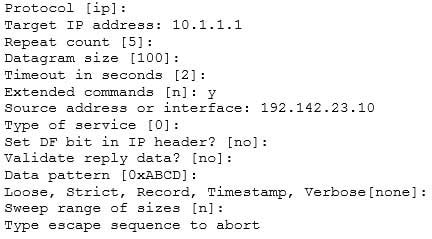
Which Cisco IOS command would prompt for input in the following format?
200-301 Part 23 Q14 210 - ping 10.1.1.1
- ping
- traceroute
- tracert
Explanation:
The extended ping command prompts the user for input in the format given in this scenario. The extended ping command is accessed by issuing a ping command without specifying an IP address. This causes the ping command to transit into extended ping command mode, where you can specify and modify various parameters, such as packet size, timeout, and repeat count.The following code is a sample partial output of the extended ping command:
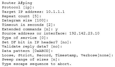
200-301 Part 23 Q14 211 The true value of the extended ping command lies in the ability to ping FROM a different device than the one you are working from. As shown in the above output, you can specify the source address on line 8.
The ping 10.1.1.1 command is incorrect because it sends an ICMP “echo request” to the target host. In turn, the target host replies with the “echo reply” packets. When pinging from one device to another on the network, ICMP and Address Resolution Protocol (ARP) are used. ARP resolves an IP address to its associated MAC addresses.
The tracert command is incorrect because this command is used by Microsoft Windows, not Cisco. It is not a valid utility to run via the Cisco IOS command-line interface. The tracert command is similar to the traceroute Cisco utility as the tracert command tests the connectivity or “reachability” of a network device or host. It reports back a reply at each hop, allowing one to determine where the communication link is “broken”.
The traceroute command is used to display the path that a packet follows to its destination. This command displays the IP address of each router in the path from the source to the destination address. Unlike the Microsoft tracert command, which uses the ICMP protocol, the Cisco traceroute command is based on User Datagram Protocol (UDP). The following code is the partial output of the traceroute command.
RouterA#traceroute 124.10.23.41

Type escape sequence to abort.
Tracing the route to 124.10.23.41

1 121.10.1.3 6 msec 6 msec 6 msec
2 134.10.10.13 30 msec 17 msec 14 msec
3 32.1.2.4 36 msec * 23 msec
Objective:
Routing Fundamentals
Sub-Objective:
Troubleshoot basic Layer 3 end-to-end connectivity issues -
You are configuring all your devices for IPv6. Which of the following is the only device that requires the ipv6 unicast-routing command?
- Layer 2 switch
- Router
- Adaptive security appliance
- Wireless AP
Explanation:
Only the router requires the ipv6 unicast-routing command. The command ipv6 unicast-routing enables the routing of IPv6 packets on a router. It is not required when you are simply configuring interfaces on devices that participate in IPv6.A Layer 2 switch can have an IPv6 address applied to its management interface and to any VLAN interfaces. However, because the switch does no routing, it does not require the ipv6 unicast-routing command.
An adaptive security appliance (ASA) can also have IPv6 addresses applied to its interfaces and can route both IPv6 and IPv4 traffic. However, it does not require the ipv6 unicast-routing command.
A wireless access point differs from a wireless router in that it operates as a switch or hub and does no routing. Therefore, it does not require this command.
Objective:
Network Fundamentals
Sub-Objective:
Configure, verify, and troubleshoot IPv6 addressing