300-410 : Implementing Cisco Enterprise Advanced Routing and Services (ENARSI) : Part 04
-
Router 5 has four interfaces. The networks hosted on each interface are as follows:
Fa0/1 192.168.5.4/29
Fa0/2 192.168.6.0/24
Fa0/3 192.168.7.0/24
S0/0 172.16.5.0/24You execute the following commands on the router:

300-410 Part 04 Q01 044 After this command sequence is executed, what routes will be present in the routing table of the router at 172.16.5.2? (Choose all that apply.)
- 192.168.5.4/29
- 172.16.5.0/24
- 192.168.6.0/24
- 192.168.7.0/24
- none of these will be present
- only network addresses beginning with 192 will be present
Explanation:
Despite the inclusion of the command aggregate-address 192.168.5.0 255.255.252.0, all subnets of the aggregate route will also be placed in the routing updates because of the omission of the summary-only keyword. Therefore, 192.168.5.4/29, 172.16.5.0/16, 192.168.6.0/24 and 192.168.7.0/24 will be present.Had the following command been executed, the subnet addresses would not appear in the routing table of the router at 172.16.5.2:Router5(config-router)# aggregate-address 192.168.5.0 255.255.252.0 summary-onlyTherefore, both the aggregate address and all of the 192.168.0.0 subnets will be in the routing table.The 172.16.5.0/24 network will be in the routing table of the router at 172.160.5.1 because it is directly connected.Objective:
Layer 3 Technologies
Sub-Objective:
Configure and verify manual and autosummarization with any routing protocol -
You manage the EIGRP subnet in your organization. You have enabled EIGRP for IPv6 on all the routers in the EIGRP AS 355 using the following commands on all the routers:
The ipv6 unicast-routing command in global configuration mode
The interface command in global configuration mode
The ipv6 enable command in interface configuration mode
The ipv6 eigrp command in interface configuration mode
The ipv6 router eigrp command in global configuration mode
The eigrp router-id command in global configuration modeDuring verification, you discover that EIGRP for IPv6 is not running on the routers.Which of the following should be done to fix the issue?
- The ipv6 address command should be executed in interface configuration mode.
- The ipv6 address command should be executed in router configuration mode.
- The eigrp router-id command should be executed in interface configuration mode.
- The eigrp router-id command should be executed in router configuration mode.
Explanation:
The eigrp router-id command should be executed in router configuration mode to fix the issue. This command specifies a fixed router IPv4 address to the router. If this command is missing or incorrectly configured on the router, EIGRP for IPv6 will not run properly.Another command that you should perform so that EIGRP for IPv6 runs on the routers is the no shutdown command. You should execute this command in interface configuration mode. The no shutdown command is necessary because all the interfaces with EIGRP for IPv6 enabled on them are in a shutdown state by default.A sample configuration to implement EIGRP for IPv6 on a router is as follows:rtrA(config)# ipv6 unicast-routing rtrA(config) # interface Fa0/1 rtrA(config-if) # ipv6 enable rtrA(config-if) # ipv6 eigrp 355 rtrA(config-if)# no shutdown rtrA(config-if) # exit rtrA(config)# ipv6 router eigrp 355 rtrA(config-rtr)# eigrp router-id 1.1.1.1
The two options stating that the ipv6 address command should be executed on the routers are incorrect. EIGRP for IPv6 can be configured on router interfaces without explicitly specifying a global unicast IPv6 address. If you specify the ipv6 enable command, as in this scenario, then the ipv6 address command is not required.
The option stating that the eigrp router-id command should be executed in interface configuration mode is incorrect. This command should be executed in router configuration mode instead of interface or global configuration modes.
Objective:
Layer 3 Technologies
Sub-Objective:
Identify IPv6 addressing and subnetting -
Which command is the proper command for allowing RIP routing updates to be received on an interface while not allowing them to be sent out of the same interface?
-
Router(config)# passive-interface e0/0
-
Router(config-if)# passive-interface
-
Router(config-if)# interface passive
-
Router(config-router)# passive-interface e0/0 -
Router(config-router)# interface passive e0/0
Explanation:
The correct answer is as follows:Router(config-router)# passive-interface e0/0The effect of the passive-interface command is dependent on the routing protocol running on the interface. For EIGRP, the router will not only stop sending routing updates, but also hellos, which means that it will not form a neighbor relationship with another EIGRP router on that interface. This is also the case with OSPF and IS-IS. With RIP, however, the router will continue to send hellos even as it stops sending routing updates, and it will still receive routing updates.The passive-interface command issued at the router configuration mode will prevent routing updates from being sent out on a specific interface while still allowing the interface to receive updates. This command can be used in any situation where you want the router to receive routing updates on a particular interface but not send any updates. This is helpful for security purposes, for preventing routing loops, or to control routing update traffic.The other options either use improper syntax or are executed at an incorrect prompt.Objective:
Layer 3 Technologies
Sub-Objective:
Configure and verify loop prevention mechanisms -
-
Examine the following diagram:

300-410 Part 04 Q04 045 Which of the following actions will make area 1 a totally stubby area? (Choose all that apply. Each correct answer is part of the solution.)
- execute the area 1 stub no-summary command on RouterA
- execute the area 1 stub no-summary command on RouterB
- execute the area 1 stub command on RouterB
- execute the area 1 stub command on RouterA
- execute the area 0 stub-no summary command on RouterA
- execute the area 0 stub no-summary command on RouterB
- execute the area 0 stub command on RouterB
- execute the area 0 stub command on RouterA
Explanation:
You should execute the area 1 stub no-summary command on RouterA and the area 1 stub command on RouterB. A totally stubby area is one that only keeps local area routes in the link-state database (LSDB), plus a default route that leads out of the area. To make an area totally stubby, the area border router (ABR) should be configured with the area 1 stub no-summary command and all other area routers should be configured with the area 1 stub command. The diagram in the scenario indicates that RouterA is the border router.You should not run any of the commands that refer to area 0. This would affect a different area than the requirement stated in the scenario.None of the other combinations of actions will create a totally stubby area.If you run the area 1 stub command on both RouterA and RouterB, it will create a stub area. A stub area differs from a totally stubby area in that a stub area will allow updates about areas in the same OSPF domain.Objective:
Layer 3 Technologies
Sub-Objective:
Configure and verify network types, area types, and router types -
Router R2 operates in a broadcast, multi-access network. Examine the following output of the show ip ospf neighbor command.

300-410 Part 04 Q05 046 Based on the output, with which routers can R2 establish a full adjacency?
- the neighbor at 192.168.5.6
- the neighbor at 192.168.5.10
- the neighbor at 192.168.5.116
- the neighbor at 192.168.5.107
Explanation:
R2 can establish a full adjacency with the neighbor at 192.168.5.107 and the neighbor at 192.168.5.165. In a broadcast, multi-access network OSPF network, full adjacencies can only be established with a designated router (DR) or a backup designated router (BDR).Objective:
Layer 3 Technologies
Sub-Objective:
Configure and verify OSPF neighbor relationship and authentication -
RouterA and RouterB are both in OSPF area 2, and RouterA is connected directly to the backbone. Their router IDs are shown below:
RouterA – 165.165.20.15
RouterB – 165.165.10.12Which commands should be executed on RouterA and RouterB to create a virtual link between the two routers?
-
RouterA(config-router)# area 2 virtual-link 165.165.10.12
RouterB(config-router)# area 2 virtual-link 165.165.20.15
-
RouterA(config-router)# area 2 virtual-link 165.165.10.12

RouterB(config-router)# area 0 virtual-link 165.165.20.15
-
RouterA(config-router)# area 0 virtual-link 165.165.20.15

RouterB(config-router)# area 2 virtual-link 165.165.10.12
-
RouterA(config-router)# area 0 virtual-link 165.165.10.12

RouterB(config-router)# area 0 virtual-link 165.165.20.15
Explanation:
The area virtual-link command should specify the area to be traversed and the ID of the router to which the router being configured will connect. Therefore, the correct answer is:RouterA(config-router)# area 2 virtual-link 165.165.10.12 RouterB(config-router)# area 2 virtual-link 165.165.20.15
A virtual link is used to make a virtual connection of an area border router (ABR) to the backbone. It is used in situations where an area does not physically border the backbone area. The virtual link provides logical connectivity of the area to the backbone. If the virtual link appears not to be functional, which would manifest itself in Router A not having all of Router B’s networks in its routing table, the state of the link can be verified on Router A by executing the show ip ospf virtual-link command. An example is shown below. The state of the link as shown in line 1 of the output should be up.RouterA# show ip ospf virtual-linksVirtual Link to router 172.16.8.2 is up
Transit area 0.0.0.1, via interface Ethernet0, Cost of using 10
Transmit Delay is 1 sec, State POINT_TO_POINT
Timer intervals configured, Hello 10, Dead 40, Wait 40, Retransmit 5
Hello due in 0:00:08
Adjacency State FULLThe configuration below is incorrect because area 0 is referenced in the second line. It should reference area 2, the area being traversed.RouterA(config-router)# area 2 virtual-link 165.165.10.12 RouterB(config-router)# area 0 virtual-link 165.165.20.15
The configuration below is incorrect because area 0 is referenced in the first line. It should reference area 2, the area being traversed.
RouterA(config-router)# area 0 virtual-link 165.165.20.15
RouterB(config-router)# area 2 virtual-link 165.165.10.12
The configuration below is incorrect because area 0 is referenced in both lines. Both should reference area 2, the area being traversed.
RouterA(config-router)# area 0 virtual-link 165.165.10.12
RouterB(config-router)# area 0 virtual-link 165.165.20.15
If the virtual link is incorrectly configured the following error will be generated:*Dec 10 00:31.146: %OSPF-4-ERRRCV: Received invalid packet mismatch area ID, from backbone area must be virtual link but not found from 165.165.10.5, Serial 0
Objective:
Layer 3 Technologies
Sub-Objective:
Configure and verify network types, area types, and router types -
-
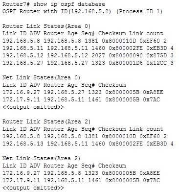
Based on the following partial output of the show ip ospf database command, which router roles(s) is Router7 performing? (Choose all that apply.)
300-410 Part 04 Q07 047 - ABR
- ASBR
- BR
- IR
Explanation:
Router7 is an area border router (ABR) and a backbone router (BR). The output reveals the link state databases for two areas, area 0 and area 2. Only ABR routers will display multiple databases when you execute this command.If Router7 is an ABR, then it is also connected to the backbone and will be a backbone router.Router 7 is not an autonomous system boundary router (ASBR) because it only displays sections in the output for Type 1 and Type 2 link-state advertisements (LSAs). ASBRs will also have a section for Type 4 LSAs, which would have its own heading at the end of the output.Router7 is not an internal router. A router is either an internal router or an ABR and Router 7 is an ABR.Objective:
Layer 3 Technologies
Sub-Objective:
Configure and verify OSPF neighbor relationship and authentication -
Examine the diagram below:
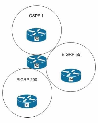
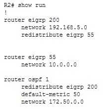
300-410 Part 04 Q08 048 Based on the diagram and the following partial output from Router R2, which networks will be present in the routing table of Router R1?
300-410 Part 04 Q08 049 - 192.168.5.0
- 10.0.0.0
- 172.50.0.0
- 192.168.5.0 and 10.0.0.0
Explanation:
The routes that will be present in Router R1 are 192.168.5.0 and 10.0.0.0. According to the output, only the route from EIGRP 55 will be redistributed to EIGRP 200. Therefore, the 10.0.0.0 network will be advertised to Router R1 from Router R2 and the 192.168.5.0 network, which is present in the routing table of Router R2, will be advertised to Router R1.The 192.168.5.0 network alone would not be correct. The 10.0.0.0 network will be present as well.The 172.50.0.0 network will not be present because Router 2 is not configured with a redistribution statement for that network. The required statement would be redistribute ospf 1.Objective:
Layer 3 Technologies
Sub-Objective:
Configure and verify redistribution between any routing protocols or routing sources -
Refer to the following diagram of an OSPF network.
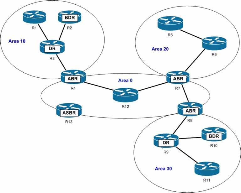
300-410 Part 04 Q09 050 Which of the following routers generate network link advertisements (NLA)? (Choose all that apply.)
- R3
- R4
- R7
- R8
- R9
- R13
Explanation:
The R3 and the R9 routers in the scenario generate network link advertisements (NLA). An NLA or a Type 2 LSA is generated only by the designated router (DR) of a segment. Type 2 LSAs are generated only for those networks in which a DR has been selected. A DR is a router that has the highest OSPF priority on a segment. Until there are two OSPF routers on the segment, no Type 2 LSAs will be generated.Type 2 LSAs are flooded in the area that contains the network segment with the DR. These advertisements are used by the DR to represent the routers that are connected to the network. This type of LSA is sent to those routers that belong to the same network as the DR. Therefore, in this case, Type 2 LSAs are generated by the R3 and the R9 routers. R3 sends the LSAs to R1, R2, and R4, while R9 sends LSAs to R8, R10, and R11.R4, R7, or R8 will not send NLAs or Type 2 LSAs. These three routers are area border routers (ABR) for different OSPF areas. Like any other OSPF router, these routers generate Type 1 LSAs or router link advertisements (RLA). The LSAs contain the state of the routers that belong to same area. In this case, R4 generates and floods Type 1 LSAs into Area 0 and Area 10. Similarly, R7 and R8 flood Type 1 LSAs into Area 0 and Area 20, and Area 0 and Area 30, respectively.ABRs also generate Type 3 and Type 4 LSAs or summary link advertisements (SLA). These LSAs are flooded into other areas to and from the backbone area. Type 3 LSAs contain the list of networks that are exchanged between two areas. In this case, R4 floods Type 3 LSAs into Area 0 and Area 10; R7 floods these LSAs into Area 0 and Area 20; and R8 floods them into Area 0 and Area 30. Type 4 LSAs list the routes that point to autonomous system boundary router (ASBR).R13 will not generate Type 2 LSAs. R13 is an Area System Border Router (ASBR), which generate Type 5 LSAs apart from Type 1 LSAs. Type 5 LSAs, or external link advertisements, list the routes external to the AS; they are flooded throughout the OSPF domain except for stub areas.Objective:
Layer 3 Technologies
Sub-Objective:
Configure and verify network types, area types, and router types -
Which of the following IPv6 addresses correctly represent the shortened version of the IP address 2031:0000:0000:130F:0000:0000:876A:130B? (Choose two.)
- 2031::130F::876A:130B
- 2031::130F:0:0:876A:130B
- 2031:0:130F::876A:130B
- 2031:0:0:130F::876A:130B
Explanation:
2031:0000:0000:130F:0000:0000:876A:130B can be shortened to either 2031::130F:0:0:876A:130B or 2031:0:0:130F::876A:130B.IPv6 addresses are written in 16-bit hexadecimal number fields separated by a colon (:). There are a total of eight 16-bit fields, making each IPv6 address a total of 128 bits. The hexadecimal letters are NOT case sensitive.You can shorten an IPv6 address by removing the leading zeros in any address field. You can only remove zeros that are the first character in an address field. For example, FFC0:02C0: is the same as FFC0:2C0:. However, FFC0:8020 is not the same as FFC0:802:.If a 16-bit address field contains all zeros, then it can be represented by a single zero. For example, FF80:0000: is the same as FF80:0:.You can use double colons (::) to represent successive address fields of zeros. An address parser can determine the number of missing fields and then insert the proper number of zeros to complete the address. For example, FF80:0000:0000:0000:0000:0000:0000:0001 is the same as FF80::1, and 0000:0000:0000:0000:0000:0000:0000:0001 could be written as ::1. However, you can only have one set of double colons (::) in an address; therefore, FF80:0000:0000:0CB0:0000:0000:0000:0001 cannot be written as F80::0CB0::1.Objective:
Layer 3 Technologies
Sub-Objective:
Identify IPv6 addressing and subnetting -
Examine the following output of the show ip ospf interface command.

300-410 Part 04 Q11 051 What would be the effect of executing the auto-cost reference bandwidth 2000 command on Router43 in router OSPF mode?
- the cost of the Serial interface would increase to 20
- the cost of the FastEthernet interfaces would increase to 2000
- the cost of the Serial interface would increase to 647
- the cost of the FastEthernet interfaces would increase to 20
Explanation:
If the auto-cost reference bandwidth 2000 command is executed in router OSPF mode it will result in a cost to the FastEthernet interfaces of 20. The formula for arriving at the cost is:reference bandwidth / interface bandwidth = costThe default reference bandwidth for FastEthernet is 100 Mbps. If the reference bandwidth is set at 2000 Mbps using the auto-cost reference command, and the FastEthernet interface has a bandwidth of 100 Mbps, the resulting cost is 20 (2000 / 100 = 20).The auto-cost reference bandwidth command is executed in router OSPF mode to affect all interfaces. Alternatively, the cost of each interface can be set separately with the ip ospf cost command issued in interface configuration mode. The two commands can also be used in combination: you can set all interfaces with the auto-cost reference bandwidth command, and then set a single interface to a different cost with the ip ospf cost command.The command would not result in the cost of the Serial interface increasing to 20 or to 647. With a reference bandwidth of 2000 Mbps and interface bandwidth of 1544 kbps (the default bandwidth of a serial interface), the resulting cost would be 1294.Objective:
Layer 3 Technologies
Sub-Objective:
Configure and verify OSPF path preference -
You instructed your assistant to configure redistribution of OSPF routes into EIGRP on Router 9. The routes are not being advertised to EIGRP and you are troubleshooting the problem. The EIGRP process ID is 100 and the OSPF process ID is 20. When you ask your assistant what commands were executed, you are shown the following:
Router9(config)# router eigrp 100
Router9(config-router)# redistribute ospf 20
What is the problem?
- no metric was configured
- the process IDs are incorrect
- the redistribute command is executed at the interface configuration prompt
- the redistribute command is executed at the global configuration prompt
Explanation:
The problem is that the metric was not configured. Some routing protocols require that a metric be provided for the redistributed routing protocol or route redistribution will not occur successfully. RIP and EIGRP both require that a metric be provided. IS-IS and OSPF do not have this requirement.When you redistribute traffic into EIGRP without specifying a metric, then the default metric applied is zero, the route will be treated as unreachable, and the route will not be advertised. The addition of the metric parameter as shown below would solve this issue:Router9(config)# router eigrp 100
Router9(config-router)# redistribute ospf 20 metric 10000 100 255 1 1500In this example, 1000 is the bandwidth, 100 is the delay, 255 is the reliability, 1 is the load, and 1500 is the MTU.The process IDs are correct in the original scenario, and the command was executed in the correct context.Objective:
Layer 3 Technologies
Sub-Objective:
Configure and verify redistribution between any routing protocols or routing sources -
Which command should be executed on all ABRs in an area to configure it as a totally stubby area?
-
Router(config-router)# area process-id stub [no-summary]
-
Router(config-router)# area area-id [no-summary] stub
-
Router(config-router)# area area-id stub [no-summary] -
Router(config-ospf)# area router-id [no-summary] stub
Explanation:
The correct syntax for the area stub command to configure a totally stubby area is shown below:Router(config-router)# area stub [no-summary]Note that the optional no-summary keyword is used only on area border routers (ABRs) to block summary link advertisements into the stub area. This option creates a totally stubby area. All internal routers in the area need only the stub keyword without the no summary keyword.It is very important to configure the command consistently on all routers within the area. OSPF sends its stub status (on or off) in its hello packets. If two neighbors have conflicting stub status, for example, if one indicates that a stub is present and the other indicates that no stub is present, they will not form an adjacency, and you end up with no OSPF communication over that link.The other options are either using incorrect syntax or being executed at an incorrect prompt. The area stub command should be executed at the OSPF router configuration prompt.Objective:
Layer 3 Technologies
Sub-Objective:
Configure and verify network types, area types, and router types -
-
You have configured a BGP network with several routers in the same autonomous system (AS). There are three possible routes from router A to router B in the network. The following conditions exist:All three routes have the same weightAll three routes were originated locally through the use of the network commandThe bgp default local-preference 50 command is executed for all three routesAll three routes have different lists of AS through which they travelWhich of the following parameters is used to select the best path among the three routes?
- Weight
- MED
- LOCAL_PREF
- AS_Path
Explanation:
The AS_Path parameter is used to select the best path among the three routes. To select the best path from router A to router B, BGP analyses various BGP attributes that are set during the configuration of the network. The key BGP attributes and the order in which they are checked are as follows:
Weight – highest weight is selected
LOCAL_PREF – highest LOCAL_PREF is selected
Locally originated routes – local routes are selected
AS_PATH – shortest AS_PATH is selected
Origin type – lowest origin type is selected
Multi-exit Discriminator (MED) – lowest MED is selectedBecause the weight attribute is same for all three routes, BGP checks the value of the LOCAL_PREF attribute. However, this attribute is also same for the three routes because the bgp default local-preference 50 command was executed for the three routes, which sets the value of the LOCAL_PREF attribute to 50 for those routes.BGP then checks whether any of the routes were locally originated using either the network or aggregate commands. As stated in the scenario, all three routes were locally originated with the network command during BGP configuration. Consequently, BGP analyzes the value of the AS_PATH attribute. This attribute refers to a list of AS numbers that are traversed by a particular route. The route with the shortest AS_PATH is selected as the best path.The weight attribute is not used to select the best path in this case. The weight attribute for all three routes is the same. If this attribute were different for the three routes, then the route with the highest weight would be considered the best path.The MED attribute is not used to select the best path in this case. The MED, or multi-exit discriminator, specifies the route into an AS that has more than one entry points. A route with the lowest MED is selected as the best path. However, in this case, the MED attribute is not considered because the AS_PATH attribute is different for the three routes. If the AS_PATH attribute for the three routes were the same, then the MED attribute would have been considered.The LOCAL_PREF attribute is not used to select the best path. The LOCAL_PREF attribute is checked if the weight attribute for the routes is same. The LOCAL_PREF attribute refers to the local preference, which specifies the route that has preference to exit the AS for a given destination network. The route with the highest LOCAL_PREF value is selected as the best path. However, the bgp default local-preference 50 command was executed for all three routes. Hence, this attribute is not considered to select the best path between the BGP routers A and B.Objective:
Layer 3 Technologies
Sub-Objective:
Explain BGP attributes and best-path selection. -
Examine the exhibit by pressing the Exhibit(s) button.
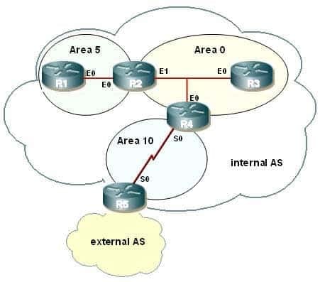
300-410 Part 04 Q15 052 You are to configure R1 to belong to area 5. This area does not accept routes from the external AS or summary routes from any other internal areas. Refer to the IP addressing below.
R1 – int E0 – 192.168.5.1/24
R2 – int E0 – 192.168.5.2/24
R2 – int E1 – 192.168.0.2/24
R3 – int E0 – 192.168.0.3/24Which configuration commands are required to correctly configure R1?
-
R1(config)# router ospf 10

R1(config-router)# area 5 no-summary stub

R1(config-router)# network 192.168.5.0 0.0.0.255 area 5
-
R1(config)# router ospf 5
R1(config-router)# area 5 stub
R1(config-router)# network 192.168.5.0 0.0.0.255 area 5
-
R1(config)# router ospf 10

R1(config-router)# area 5 stub

R1(config-router)# network 192.168.5.0 255.255.255.0 area 5
-
R1(config)# router ospf 5

R1(config-router)# area 5 stub no-summary

R1(config-router)# network 192.168.5.0 255.255.255.0 area 5
Explanation:
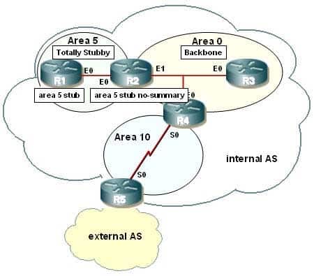
All routers within a stub area must be configured as stub, or adjacencies will not form. Besides the command to enable OSPF and the command to identify the area, the only other required command identifies the area as a stub. At the area border router (ABR), R2, the no-summary keyword is required. The following commands are required to configure R1:R1(config)# router ospf 5
R1(config-router)# area 5 stub
R1(config-router)# network 192.168.5.0 0.0.0.255 area 5A totally stubby area does not accept any external network LSAs (Type 5) or any inter-area summary LSAs (Types 3 and 4) from entering the area. Use the area stub command with the no-summary keyword on the ABR only to configure a totally stubby area.The correct syntax for the area stub command is shown below:Router(config-router)# area area-id stub [no-summary]Note that the optional no-summary keyword is used only on ABRs to block summary link advertisements into the stub area. This option creates a totally stubby area. It is very important to configure the command consistently on all routers within the area. OSPF sends its stub status (on or off) in its hello packets.If two neighbors have conflicting stub status, they will not form an adjacency, and you end up with no OSPF communication over that link.
300-410 Part 04 Q15 053 Objective:
Layer 3 Technologies
Sub-Objective:
Configure and verify network types, area types, and router types -
-
Which of the following commands will display information about Type 4 LSAs?
-
show ip ospf database external
-
show ip ospf database asbr-summary -
show ip ospf database summary
-
show ip ospf database router
Explanation:
The command show ip ospf database asbr-summary will display information about Type 4 LSAs. These LSAs provide next-hop information for areas that are receiving Type 5 or external LSAs. Consider the following sample output of the show ip ospf database asbr-summary command:
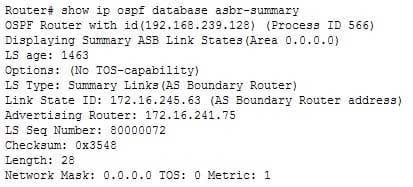
300-410 Part 04 Q16 054 The output shows that the router that sent this LSA is at 172.16.241.75. The router functioning as the ASBR is at 172.16.245.63. The advertising router, located at 172.16.241.75, is broadcasting that its best metric to reach the ASBR at 172.16.254.63 is 1.
The command show ip ospf database external will not display information about Type 4 LSAs. It will display information about Type 5 LSAs, or External Link LSAs, instead of ASBR summary links, which are Type 4 LSAs.
The command show ip ospf database summary will not display information about Type 4 LSAs. It will display information about summary links, or Type 3 LSAs, that are generated by an ABR, not summary links generated by an ASBR.
The command show ip ospf database router will not display information about Type 4 LSAs. It will display information about router links, or Type 1 LSAs, instead of ASBR summary links, which are Type 4 LSAs.
Objective:
Layer 3 Technologies
Sub-Objective:
Describe OSPF packet types -
-
You have a router that is running both OSPF and RIP. You have configured this router to perform mutual redistribution between the two protocols. The following conditions exist:
The S0/0 interface, which is configured for RIP, is routing for the 172.16.5.0/24 network.
The S0/1 interface, which is configured for OSPF, is routing for the 172.16.6.32/28 network.Users in the RIP domain are unable to connect to devices in the OSPF domain.What must be done to allow the OSPF routes to be redistributed into the RIP domain? (Choose two. Each correct answer is part of the solution.)
- Create a static route that points to 172.16.6.0/24 with a next hop of null0.
- Execute the passive-interface command on S0/0.
- Create a loopback address on the router
- Redistribute static routes into RIP.
Explanation:
The OSPF domain has a different mask than the RIP domain, and they are on the same major network. The OSPF domain’s mask is also longer than the RIP domain’s mask. Therefore, the RIP domain will not advertise routes learned from OSPF and redistributed into RIP. To solve this problem, you can create a static route to the major (classful) network 172.16.6.0/24, which includes all of the subnets in the OSPF domain, set the destination as null0, and then redistribute static routes into RIP. The following commands would enable this process:router1(config)# ip route 172.16.5.0 255.255.255.0 null0 router1(config)# router rip router1(config-router)# redistribute static router1(config-router)# default metric 1
You should include the metric as well to ensure redistribution. This will allow the 172.16.5.0/24 network to be advertised to the RIP domain and, when the frames arrive at the null0 interface, will ensure the routing table of the router will have routes to the specific subnets of the OSPF domain.
You should not execute the passive-interface command. This would prevent the interface from advertising either RIP or OSPF routes, and would only allow RIP updates inbound. This would not solve the problem and will create additional problems when the router is unable to advertise RIP routes to the other routers in the RIP domain.
You should not create a loopback address on the router. Loopback addresses are logical addresses that can be created and used as the source of routing updates. Under normal circumstances, if routing updates are sourced from a physical interface and the interface goes down, the route will be removed from the routing tables. Since a loopback interface cannot go down, it provides the advantage of keeping a route in the tables even if the physical interface that services the route goes down. Loopback interfaces are of no help in solving the redistribution problem.
Objective:
Layer 3 Technologies
Sub-Objective:
Configure and verify manual and autosummarization with any routing protocol -
You are the network administrator for a large software organization. You designed the LAN in the organization’s main building for connecting the internal LAN to a WAN as shown below:

300-410 Part 04 Q18 055 You have configured EIGRP with the variance parameter set to 3 on all the routers to enable unequal load balancing from the 172.16.1.0 network to the WAN. The delay configured on each of the routers is shown in the LAN diagram, and the K values are set as follows:
K1 = 0
K2 = 0
K3 = 1
K4 = 0
K5 = 0Which of the following paths are entered into the routing tables as a result of the unequal load balancing configured on the routers? (Choose all that apply.)
- RA-RB-RD-RH-RK
- RA-RB-RE-RI-RK
- RA-RC-RF-RI-RK
- RA-RC-RG-RJ-RK
Explanation:
The only path is entered in the routing table as a result of the unequal load balancing configured on the routers:RA-RB-RE-RI-RKIn EIGRP networks, bandwidth and delay are the default factors for calculating the metric/cost for a given route. Additional factors such as load and reliability can be considered in the computation of the EIGRP metric, as given in the following formula:Metric = [K1 * bandwidth + (K2 * bandwidth) / (256 – load) + K3 * delay] * [K5 / (reliability + K4)]In this case, only the K3 value has a non-zero value. This implies that only delay is taken into consideration to calculate the metric of the shortest path from 172.16.1.0 network to the WAN. The path with the lowest metric, which is delay in this scenario, is the shortest path, and is therefore entered automatically in the routing table. The total delay and the corresponding metric for the three best paths are given as follows:In the given table, the path RA-RB-RE-RI-RK has the lowest metric of 14080. This is the shortest path, so it would be entered in the routing table even if variance were not enabled. In this scenario variance is set to 3, which enables unequal load balancing among those paths that have a metric less than three times the least metric for the given route. Three times the least metric in this scenario is 42240 (14080 x 3). This implies that paths between the 172.16.1.0 network and the WAN having a metric less than 42240 participate in the load balancing. On metric values alone, those paths would appear in the routing tables. However, to be eligible to be a feasible successor the reported distance of the path must be less than the feasible distance (current best path). None of the paths, with the exception of RA-RB-RE-RI-RK meet that requirement.
The path RA-RB-RD-RH-RK is not entered in the routing table as a result of the unequal load balancing. The scaled EIGRP delay for this path is 43520 (170 x 256), which is more than three times the least metric available from the 172.16.1.0 network to the WAN (42240). In addition, the reported distance for this path is more than the feasible distance. Therefore, the path RA-RB-RD-RH-RK is not used for balancing the load from the 172.16.1.0 network to the WAN and does not appear in the routing tables.
Objective:
Layer 3 Technologies
Sub-Objective:
Configure and verify EIGRP load balancing -
OSPF area border routers (ABRs) advertise a default route to stub and totally stubby areas.Which command is the BEST command to configure a cost of 25 for the default route advertised to area 1?
-
Router(config-router)# area 1 cost 25
-
Router(config-router)# area 1 default 25
-
Router(config-router)# area 1 default-cost 25 -
Router(config-router)# area 1 default-route-cost 25
Explanation:
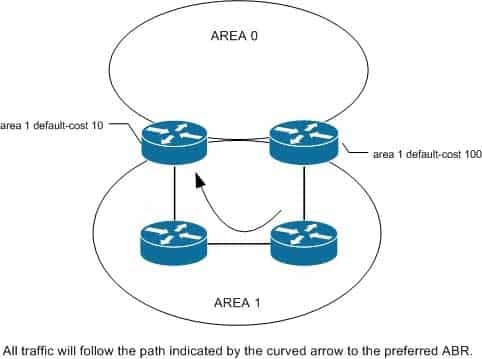
The correct answer is area 1 default-cost 25. Even though another option (area 1 default 25) is a configurable abbreviation for the command, the more correct answer explicitly specifies the default-cost parameter. The correct syntax for the area default-cost command is shown below:Router(config-router)# area area-id default-cost cost
If you have multiple border routers between two areas, you might prefer one exit-point router over the other for that area. By configuring one with a lower cost than the other, it will become the preferred exit point. If that router or its links were to fail, then the routers interior to the area would route through the second-best exit point. You could also set the default costs to values that are close to achieve better load balancing. The default default-cost is 1. Please see the network shown in the graphic.
300-410 Part 04 Q19 056 Objective:
Layer 3 Technologies
Sub-Objective:
Configure and verify OSPF path preference -
-
You need to manually assign IPv6 addresses to the interfaces on an IPv6-enabled router. While assigning addresses, you need to ensure that the addresses participate in neighbor discovery and in stateless auto-configuration process on a physical link.Which of the following addresses can be assigned to the interfaces?
- FEC0:0:0:1::1/64
- FE80::260:3EFF:FE11:6770/10
- 2001:0410:0:1:0:0:0:1/64a
- 2002:500E:2301:1:20D:BDFF:FE99:F559/64
Explanation:
The FE80::260:3EFF:FE11:6770/10 address can be assigned to an interface of the IPv6-enabled router. This address is a link-local address as it has the prefix FE80::/10. Link-local addresses can be configured for an interface either automatically or manually.Link-local addresses are IPv6 unicast addresses that are configured on the interfaces of an IPv6-enabled router. With link-local addresses, the nodes can connect to a network (local link) and communicate with other nodes. In addition, these addresses participate in the neighbor discovery protocol and the stateless auto-configuration process.
The FEC0:0:0:1::1/64 address should not be used for the interfaces because this address is a site-local address. Site-local addresses are IPv6 equivalent addresses to IPv4’s private address classes. These addresses are available only within a site or an intranet, which typically is made of several network links.
You should not use the 2001:0410:0:1:0:0:0:1/64 and 2002:500E:2301:1:20D:BDFF:FE99:F559 addresses for the interfaces. These two addresses are global unicast addresses as they fall in the range from 2000::/3 and to E000::/3. A global address is used on links that connect organizations to the Internet service providers (ISPs).
Objective:
Layer 3 Technologies
Sub-Objective:
Identify IPv6 addressing and subnetting