300-410 : Implementing Cisco Enterprise Advanced Routing and Services (ENARSI) : Part 05
-
Examine the exhibit.

300-410 Part 05 Q01 057 What additional EIGRP configuration is required to ensure that all destination networks are reachable if all routers are running pre- 15.0 versions of the IOS?
- The eigrp stub receive only command should be executed on routers A and B.
- A static route to 10.10.0.0/16 via the interface to router D should be configured at router C.
- The no auto-summary router configuration command should be executed on router C.
- The passive interface command should be executed on routers A and B.
- The no auto-summary command should be executed on routers A and B.
Explanation:
To ensure the full network is reachable, routers A and B must advertise their networks without first summarizing them to the class B 172.31.0.0/16 address in updates to router C. Otherwise, router C would incorrectly assume that it has two paths to the 172.31.0.0 classful network: one via router A and the other via router B. Therefore, routers A and B should be configured with the no auto-summary command so that they advertise 172.31.16.0/24 and 172.31.17.0/24, respectively. Starting with version 15, EIGRP auto summarization is disabled by defaultSummarization is beneficial in most cases. It reduces the number of routes in the neighboring router tables and effectively contains EIGRP queries. The problem with discontiguous networks (or subnets) using EIGRP is that EIGRP will automatically summarize on the classful network boundary. By configuring the router to disable automatic summarization with the no auto-summary command, the routers will be able to see all of the individual subnets, not just a summary. The no auto-summary command must be issued from router configuration mode as shown below:
router(config-router)# no auto-summary
Note that auto summarization is effective only on directly connected routes. For example, in the scenario exhibit, router C does not need to have auto summarization disabled in order to advertise the subnets to routers D and E. Since those subnet routes were learned via a route advertisement, they will be advertised to routers D and E without summarization.
In some situations, it may be necessary to turn off auto summarization globally while still summarizing specific networks. If you need to manually summarize a set of networks, the following command when executed in EIGRP configuration mode can summarize those specific networks while auto summarization is disabled:
ip summary-address [eigrp as-number] [address] [mask]
For example:
router10(config)# int Ethernet0/0
router10(config-if)# ip summary-address eigrp
Objective:
Layer 3 Technologies
Sub-Objective:
Configure and verify manual and autosummarization with any routing protocol -
You are configuring EIGRP on a spoke router in a hub-and-spoke topology. In an effort to keep the routing table small, the hub router has been configured to send only a default route to the remote routers.
What command would you use on the spoke routers to enable them to send only connected and summary routes to the hub router, and prevent the hub router from sending a query to the spoke router when a route is lost elsewhere?
- eigrp stub
- eigrp stub static
- eigrp passive
- eigrp stub receive-only
Explanation:
The eigrp stub command is used to configure a router to send only connected and summary routes to its neighboring router. For example, examine the following output of the show ip route command that was executed on a router configured as a stub router:router10#show ip route C 172.16.5.0/24 is directly connected, Serial 0 D 192.168.7.0/24 [90/16523564] via 172.16.4.1, 00:21:20, Serial 1 D 172.16.0.0/16 is a summary, 00:21:23, Null 0 C 172.16.4.0/24 is directly connected, Serial 2
The routes that will be advertised are 172.16.5.0/24, 172.16.4.0/24, and the summary route 172.16.0.0/16. The first two is directly connected routes, and the last is the summary route that is auto configured by the EIGRP process.
When the stub feature is enabled on a router, the router will announce itself as a stub router. Neighbor routers will not query a stub router for alternate routes when a route is lost elsewhere in the network. The EIGRP stub feature works well in hub-and-spoke topologies when the goal is to minimize the amount of EIGRP bandwidth and processing associated with the spoke router. The eigrp stub command has the following syntax:
eigrp stub [receive-only | connected | static | summary]
When you do not specify any keywords with the command, connected and summary are used by default.
receive-only: Prevents the router from sending any connected or summary routes.
connected: Instructs the router to send connected routes.
static: Instructs the router to send static routes that were redistributed by using the redistribute static command.
summary: Instructs the router to send summary routes.These parameters can be combined to resolve various problems, as seen in the following image:

300-410 Part 05 Q02 058 Router A is not receiving the route to the 172.16.1.0/16 network because Router B, which stands between Router A and C, is configured with the eigrp stub-receive-only command. This is resulting in hosts from the corporate office being unable to connect to hosts in the 172.16.0.0/16 network. If there were a legitimate reason to keep Router B configured with the eigrp stub-receive-only command, the problem could be solved by executing the following command set on Router A:
routerA(config)# router eigrp 20
routerA(config-router)# ip summary-address eigrp 20 172.16.0.0 255.255.0.0
routerA(config-router)# eigrp stub connected summary
This command set would create a summary address for the 172.16.0.0/16 network and then advertise it to the corporate office as a result of using the eigrp stub connected summary command. The inclusion of the connected parameter ensures that the directly connected networks will also be advertised, to ensure that hosts in the corporate office can reach the 172.16.0.0/16 network.
The eigrp stub static command instructs the router to send static routes that were redistributed by using the redistribute static command. Examine the EIGRP configuration shown below:
<output omitted>
ip route 10.4.4.0 255.255.255.0 10.4.3.10
Route eigrp 200
No auto-summary
Redistribute static 1000 1 255 1 1500
Network 10.4.1.0 0.0.0.3.
Network 10.4.2.0 0.0.0.255
Eigrp stub staticWith this configuration, the router would not advertise any of the networks defined in the network statements, but would only advertise the static route configured with the line ip route 10.4.4.0 255.255.255.0 10.4.3.10.
Eigrp passive is not a valid Cisco command.
Eigrp stub receive-only will cause the router to not advertise any routes. The router will only receive updates.
Objective:
Layer 3 Technologies
Sub-Objective:
Configure and verify EIGRP stubs -
Which conditions will prevent two EIGRP routers from becoming neighbors? (Choose two.)
- Their K-values do not match.
- Their hold times do not match.
- Their AS numbers do not match.
- Their hello intervals do not match.
Explanation:
EIGRP routers will not become neighbors if the K-values do not match or if the autonomous system (AS) numbers do not match. They also will not become neighbors if EIGRP is not enabled for the proper networks on the local and remote routers. However, routers can become neighbors if their hello intervals and hold times do not match.The AS number is designed to control the routers with which a router can communicate. If the AS numbers do not match, EIGRP will not exchange routes between the two routers by design and definition.
The K-values are flags that state whether a certain metric component, such as Load, is used. They must match because they regulate how the metric values are calculated. If one router is just using bandwidth and delay to calculate its metric, and another is using bandwidth, delay, and load; they could make contradictory routing decisions that would lead to a routing loop. Because of this possibility, EIGRP requires that the K-values must match before it will allow the routers to exchange routes.
EIGRP does not require that the hello and hold times match. Although this flexibility can be helpful, it can also lead to unforeseen problems if they are accidentally mismatched. The hello interval is the amount of time in seconds to wait before sending another hello packet. The hold time is the amount of time in seconds to wait before declaring a link to be down.
Objective:
Layer 3 Technologies
Sub-Objective:
Configure and verify EIGRP neighbor relationship and authentication -
Click the Exhibit(s) button to view an EIGRP network. The partial output of the show running-config command on the rtrB router is as follows:

300-410 Part 05 Q04 059 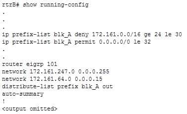
300-410 Part 05 Q04 060 Which of the following subnets are blocked through the Fa0/0 interface of rtrB while sending updates to rtrC? (Choose all that apply.)
- 172.161.9.0/24
- 172.161.35.0/18
- 172.161.64.0/28
- 172.161.88.0/22
- 172.161.111.0/25
- 172.161.247.0/30
Explanation:
The 172.161.9.0/24, 172.161.111.0/25 and 172.161.247.0/30 subnets are blocked through the Fa0/0 interface of rtrB while sending updates to rtrC. The following lines in the output create an IP prefix list named blk_A:ip prefix-list blk_A deny 172.161.0.0/16 ge 24 le 30
ip prefix-list blk_A permit 0.0.0.0/0 le 32The blk_A list blocks the subnets that exactly match the first 16 most significant bits as 172.161.0.0. The ge keyword indicate that the subnet mask for the 172.161.0.0 subnets must be greater than or equal to 24 bits. Similarly, the le keyword indicates that the mask for the 172.161.0.0 subnets should be less than or equal to 30 bits. Therefore, all subnets of 172.161.0.0 network with masks 24, 25, 26, 27, 28, 29, and 30 are blocked.
The second line permits all other routes to be passed on. The subnets that match the blk_A prefix list are 172.161.9.0/24, 172.161.111.0/25, 172.161.247.0/30, and 172.161.64.0/28.
The line distribute-list prefix blk_A out indicates that the distribute-list command applies the blk_A prefix list to all the outgoing interfaces. This implies that if rtrB receives an update about the 172.161.9.0/24, 172.161.111.0/25, 172.161.247.0/30 or 172.161.64.0/28 subnets, they are blocked. In this case, the 172.161.64.0/28 is not blocked through the Fa0/0 interface to rtrC because it is directly connected.
The 172.161.35.0/18 and 172.161.88.0/22 subnets are not blocked through the Fa0/0 interface of rtrB to rtrC. This is because both these subnets are outside the range of prefix masks 24 through 30; hence, these two subnets are allowed through the Fa0/0 interface.
Objective:
Layer 3 Technologies
Sub-Objective:
Configure and verify filtering with any protocol -
Refer to the following exhibit.
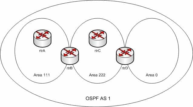
300-410 Part 05 Q05 061 You executed the following commands on all three routers in OSPF AS 1:
The ipv6 cef command in the global configuration mode
The interface serial command in the global configuration mode
The ipv6 address command in the interface configuration mode
The ipv6 ospf area command in the interface configuration modeYou run the show ipv6 traffic command and observe that IPv6 packets are not being exchanged between the OSPF routers.
Which of the following commands should be configured on the routers to fix the problem?
- ipv6 enable
- ip address
- ipv6 router ospf
- ipv6 unicast-routing
Explanation:
The ipv6 unicast-routing command should be used on all of the routers to rectify the problem. The ipv6 unicast-routing command allows the forwarding of IPv6 packets. You should execute the ipv6 unicast-routing command in the global configuration mode.A sample configuration to enable OSPF for IPv6 on the S0/1 interface of rtrA is as follows:

300-410 Part 05 Q05 062 The ipv6 enable command is not required if an IPv6 address has been configured on an interface. If it is executed with no IPv6 addresses configured, the interfaces will use the link local IPv6 addresses that each interface generates automatically.
The ip address command is not required to fix the problem because this command is used to specify an IPv4 address to a router interface. The use of this command depends on the type of tunneling mechanism used. In this case, no tunneling mechanism is being used.
The ipv6 router ospf command does not rectify the problem because this command is used to enter the router configuration mode for OSPF for IPv6. Using this command is optional and does not affect the activation of OSPF for IPv6 on the routers.
Objective:
Layer 3 Technologies
Sub-Objective:
Configure and verify OSPF for IPv6 -
The exhibit contains portions of RouterA’s BGP configuration and IP routing table.
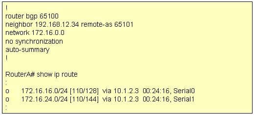
300-410 Part 05 Q06 063 Which IP network addresses, that were not learned using BGP, will be present in BGP advertisements from RouterA?
- 172.16.0.0/16
- 172.16.16.0/24
- 172.16.24.0/20
- No IGP networks will be advertised because synchronization is disabled.
Explanation:
The auto-summary command can affect which networks, identified by using the network command, will be advertised. Using the existing BGP configuration, the router will not announce the 172.16.16.0/24 subnet. Instead, it will announce the classful address 172.16.0.0/16 when the IP routing table maintained by the IGP contains any subnet of that classful address.The network command directly affects what network is advertised in BGP. If the network command does not also include a network mask, and if auto-summary is enabled, the classful address of 172.16.0.0/16 is advertised any time that the router learns about a 172.16.0.0 subnet via its Interior Gateway Protocol (IGP), such as OSPF or EIGRP. In the exhibit, the routing table does contain entries of the 172.16.16.0/24 and 172.16.24.0/24 subnets that were learned by using the IGP.
If auto-summary is disabled by using the no auto-summary command, only networks in the routing table that are exact matches to the network commands are advertised. For example, to have the router announce only the 172.16.16.0/24 subnet learned via its IGP, you should alter the network command’s IP address and include the subnet mask as follows:
network 172.16.16.0 mask 255.255.255.0
A combination of network statements and route statements can be used to advertise a subset of networks that exist. Examine the output shown below:
router bgp 68410
network 192.168.24.0 255.255.252.0
neighbor 172.16.8.5 remote-as 68441
ip route 192.168.24.0 255.255.252.0 null 0The router is configured to advertise a summary route to the network 192.168.24.0 255.255.252.0. Consider the following networks:
192.168.24.0/24
192.168.25.0/24
192.168.26.0/24
192.168.32.0/24If this router was connected to those networks, and received a packet destined for 192.168.25.1, it would successfully route the packet because the summary address (where the summarization is the result of the mask 255.255.252.0) is designed to include all of the subnets above except for 192.168.32.0/24. Therefore, all subnets except 192.168.32.0/24 will be advertised by the network and ip route statements with the summary mask.
Note: Whenever changes are made to a routing policy or to an access list that is used by a routing policy, the change will not be reflected in the routing tables of the receiving routers until the BGP session has been cleared with the clear ip bgp command.
The BGP synchronization rule specifies that networks will not be advertised or used via iBGP unless it also has been learned through an IGP. If synchronization is disabled, iBGP will advertise a network without also learning it through an IGP.
Objective:
Layer 3 Technologies
Sub-Objective:
Configure and verify eBGP (IPv4 and IPv6 address families) -
You are configuring BGP speakers RouterA and RouterB to authenticate one another. The following conditions exist:
RouterA has an IP address of 192.168.5.3
RouterB has an IP address of 192.168.5.2
Both routers reside in AS 6550.
Which of the following commands will result in successful authentication?
- neighbor 192.168.5.2 password routera executed on RouterA
neighbor 192.168.5.3 password routerb executed on RouterB - neighbor 192.168.5.2 password routerb executed on RouterA
neighbor 192.168.5.3 password routera executed on RouterB - neighbor 192.168.5.2 password routera executed on RouterA
neighbor 192.168.5.3 password routera executed on RouterB - neighbor 192.168.5.2 password routera executed on RouterA
- neighbor 192.168.5.2 password routerb executed on RouterB
Explanation:
The following command pair should be used to configure successful authentication:neighbor 192.168.5.2 password routera executed on RouterA neighbor 192.168.5.3 password routera executed on RouterB
When setting the keys for authentication, the keys must match. The keys do not need to be the names of either router, and should be a combination of letters numbers and symbols. In this example, both keys are set to the value routera.
The following two command pairs are incorrect because the keys do not match:
neighbor 192.168.5.2 password routera executed on RouterA
neighbor 192.168.5.3 password routerb executed on RouterB
and
neighbor 192.168.5.2 password routerb executed on RouterA
neighbor 192.168.5.3 password routera executed on RouterB
If you executed the debug ip bgp command to perform troubleshooting with either of these configurations in place, the error message you would see would be as follows:
%TCP-6-BADAUTH: Invalid MD5 digest from 192.168.5.3 (12293) to 192.168.5.2 (179)
In the error message, the numbers in parentheses are the port numbers used for the attempted communication.
The single commands would be incorrect because the key has only been configured on one end:
neighbor 192.168.5.2 password routera executed on RouterA
and
neighbor 192.168.5.2 password routerb executed on RouterB
If you executed the debug ip bgp command to troubleshoot with either of these configurations in place, you would see the following message:
%TCP-6-BADAUTH: No MD5 digest from 192.168.5.3 (12293) to 192.168.5.2 (179)
Objective:
Layer 3 Technologies
Sub-Objective:
Describe, configure, and verify BGP peer relationships and authentication - neighbor 192.168.5.2 password routera executed on RouterA
-
If you executed the show ip ospf database command, which keyword would you add to the command to produce the following output?

300-410 Part 05 Q08 064 - router
- summary
- network
- external
Explanation:
The output was produced with the summary keyword. When the show ip ospf database command is executed, any of several keywords can be used to specify the type of link-state advertisements (LSAs) to display. The output LS Type: Summary Links(Network) indicates that these are summary links. Summary LSAs are generated by an area border router (ABR) and will be displayed when you execute the summary keyword. These are Type 3 LSAs.The router keyword was not used. If this keyword had been used, the LS Type line would have included Router Links instead of Summary Links. Router LSAs are Type 1 LSAs.
The network keyword was not used. If this keyword had been used the LS Type line would have included Network Links instead of Summary Links. Network LSAs are Type 2 LSAs.
The external keyword was not used. If this keyword had been used the LS Type line would have included AS External Links instead of Summary Links. External LSAs are Type 5 LSAs.
Objective:
Layer 3 Technologies
Sub-Objective:
Describe OSPF packet types -
With respect to modifying an OSPF router ID to a loopback address, which of the following statements are true?
- OSPF is not as reliable if a loopback interface is configured.
- Using a loopback address avoids wasting an additional IP address.
- A loopback interface is not always active, and it can go “down” like a real interface.
- The loopback address does not automatically appear in the routing table of neighboring OSPF routers, so it cannot be pinged from other routers unless you include it with a network statement on the router local to the loopback interface.
Explanation:
A loopback address does not automatically appear in neighboring routers’ routing tables, so it cannot be pinged for network troubleshooting.A work-around for this problem is to add a network statement under OSPF that advertises the loopback address network so that other routers will know how to reach your loopback.
A loopback address is an IP address assigned to a loopback interface, which is a logical interface on a router that behaves like a physical interface. Their advantage is that, unlike physical interfaces, logical interfaces do not go down.
For example:
Router(config)# interface loopback 0
Router(config-if)# ip address 172.17.1.1 255.255.255.0
In the example, a loopback IP address is used by OSPF to provide its router ID. This type of address is preferred because it is assumed to be more stable than a router ID tied to a physical interface. The traditional problem with a router ID tied to a physical interface is that if the physical interface were to go down, the router would have to change its router ID to some other value. That would cause the OSPF neighbor relationships to reset and change values in the link-state advertisements (LSAs), causing a disruption to the OSPF area.
With this consideration in mind, OSPF is more reliable when using a loopback interface than using a physical interface.
Using a loopback address does not avoid wasting an additional IP address. The address must still be unique.
A loopback interface is always active, and it cannot go “down” as a physical interface can.
Objective:
Layer 3 Technologies
Sub-Objective:
Configure and verify OSPF operations -
Which of the following commands need to be configured on a RIPng router prior to enabling this routing protocol?
- ipv6 rip enable
- ipv6 multicast-routing
- ipv6 unicast-routing
- ipv6 router rip
Explanation:
The ipv6 unicast-routing command should be used before enabling RIPng on a router. This command should be executed in global configuration mode of the router. IPv6 can then be enabled by using the ipv6 enable command on any of the interfaces of the router. The ipv6 unicast-routing command allows you to forward IPv6 unicast datagrams.
Routing Information Protocol Next Generation (RIPng) allows routers to learn about routes in an autonomous system. RIPng is an extension of the RIPv2 protocol to provide support IPv6 for future adherence.
The similarities between RIPv2 and RIPng are as follows:
Both protocols use User Datagram Protocol (UDP).
Both use distance vector algorithm to find the best route.
Both of them measure the metric in terms of hops.
Both have the same maximum hop count of 15 for valid routes.The differences between RIPv2 and RIPng are as follows:RIPv2 learns IPv4 routes, whereas RIPng learns IPv6 routes
RIPv2 supports automatic summarization as IPv4 defines classful addresses, whereas RIPng does not support automatic summarization
RIPv2 uses UDP port 520, whereas RIPng supports port 521
RIPv2 requires authentication for RIP packets, whereas RIPng does not require RIP-specific authentication as IPv6 has an in-built IPsec authenticationThe ipv6 rip enable command should not be used because this command allows you to enable IPv6 RIP routing process on the interfaces of a router.You should not use the ipv6 multicast-routing command prior to enabling IPv6 on the router. This command is used after IPv6 is enabled on one or more interfaces of the router to allow multicast forwarding using Protocol Independent Multicast (PIM) and Multicast Listener Discovery (MLD) on all the IPv6-enabled interfaces.The ipv6 router rip command should not be used prior to enabling IPv6 because it allows you to enter the RIP for IPv6 router mode.Objective:
Layer 3 Technologies
Sub-Objective:
Describe RIPng -
Which statements in regards to route filtering are true? (Choose two.)
- Network security is the primary role of route filtering.
- If no route filter exists for an interface, the packet is processed normally.
- Route filtering on an interface cannot filter routes that originate from the same router.
- The distribute-list command enables the administrator to filter redistributed routes.
- The network keyword of the passive-interface command enables you identify the routes to advertise.
Explanation:
Distribute lists are used to filter inbound, outbound, or redistributed routing updates. Instead of using the passive-interface command, distribute lists enable you to selectively control which routes are processed.If no distribute list is associated with the interface, the routing update packets are processed normally.
If a distribute list is associated with an interface, the routing update is compared to the access list that was specified in the distribute list. If a match is found to a permit statement, then the packet is forwarded. If a match is found to a deny statement, the packet is discarded. If no match is found, the implicit deny statement at the end of the access list will drop the packet.
Network security is not the primary role of route filtering. Its primary function is to reduce unnecessary routing update traffic.
Route filtering on an interface can filter routes that originate from the same router.
The network keyword of the passive-interface command does not enable you identify the routes to advertise.
Objective:
Layer 3 Technologies
Sub-Objective:
Configure and verify filtering with any protocol -
By default, how often are EIGRP hello packets sent on a LAN?
- 5 seconds
- 10 seconds
- 30 seconds
- 60 seconds
Explanation:
The EIGRP default hello time over a LAN or high-speed dedicated WAN link is five seconds.On multipoint circuits with less than T1 bandwidth, EIGRP hello packets are sent every 60 seconds.
EIGRP sets the default hello interval to five seconds to ensure that it can quickly sense if connectivity to a neighboring router has been cut. If a router does not hear from a neighboring EIGRP router in 15 seconds, it will declare that neighbor as no longer reachable.The five-second hello interval is shorter than the default values for OSPF hellos (10 seconds), RIP updates (30), or IGRP updates (90). As a result, EIGRP senses network faults faster by default than do other protocols.
Objective:
Layer 3 Technologies
Sub-Objective:
Configure and verify EIGRP neighbor relationship and authentication -
Which of the following commands allows a Cisco router to obtain an IP address from a DHCP server?
-
Router(config-if)# ip address dhcp -
Router(config)# ip address dhcp
-
Router(dhcp-config)# ip address dhcp
-
Router(config)# address dhcp
-
Router(dhcp-config)# address dhcp
Explanation:
The ip address dhcp command when issued from interface configuration mode will allow a router to obtain an IP address for that interface from a DHCP server.In this scenario, the router is acting as a DHCP client, not a server, so the command would not be issued from dhcp-config mode. In addition, the IP address is being assigned to an interface on the router, not the router as a whole so the command would not be entered at global config mode.
The most common situation in which a router interface might be set as a DHCP client is to enable one DHCP router to obtain configuration options from another router providing this service.
Consider an example where RouterA is connected to RouterB. RouterA contains a complete DHCP configuration including the options (DNS server, domain name). RouterB is connected to RouterA through its FastEthernet0 interface. The following configuration would allow RouterB to issue a different set of addresses than RouterA while importing the options from Router A. The configuration of RouterB is below as shown in the partial output of the show run command:
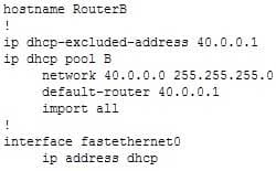
300-410 Part 05 Q13 065 Note that for this configuration to function properly, the FastEthernet0 interface on RouterB must be set as a DHCP client.
The command router(config)# ip address dhcp is incorrect because it is executed at the global configuration prompt. The command must be executed in interface configuration mode.
The command router(dhcp-config)# ip address dhcp is incorrect because it is executed at the DHCP configuration prompt. The command must be executed in interface configuration mode.
The command router(config)# address dhcp is incorrect because it is missing the ip part of the command.
The command router(dhcp-config)# address dhcp is incorrect because it is missing the ip part of the command and it is executed at the DHCP configuration prompt. It must be executed in interface configuration mode.
Objective:
Layer 3 Technologies
Sub-Objective:
Identify, configure, and verify IPv4 addressing and subnetting -
-
Which statements about BGP policy-based routing are true? (Choose two.)
- BGP policy-based routing is performed on a router’s inbound interface.
- A BGP administrator can use policy-based routing to alter the final destination of the packet.
- BGP policy-based routing will select the next-hop of the packet based on its source address.
- BGP policy-based routing can be used to alter the path selection for a packet in a downstream AS.
Explanation:
BGP policy-based routing is performed on a router’s inbound interface. BGP policy-based routing will select the next-hop of the packet based on its source address. It does this through the use of route maps.Below is a partial output of the show run command executed on a router that has a BGP configuration that uses a route map to alter the local preference of a route (172.16.0.0/16) to 90 if it is advertised from the BGP neighbor at 10.5.5.1:

300-410 Part 05 Q14 066 The above output indicates that the local preference for the route to 172.16.0.0/16 is 90 ONLY if it comes from 10.5.5.1, but not if the same route is advertised from 10.5.5.35.
Route maps can be used to influence a part of the routing table without affecting the rest of the table. Consider an example where a router had two routes to every network in the table, and it prefers Neighbor A as the next hop for all routes. If you desired to change the next hop for one of the routes to Neighbor B without affecting the others, you could use route maps to take two different approaches, altering different attributes, which would arrive at the same result. The approaches would be:
Apply a route map to Neighbor B incoming that would set the local preference to 200 (default is 100) for the route. Local preference values determine the path used to exit the AS. A higher value is preferred.
Apply a route map to Neighbor A such that it advertises the route with a MED of 200. Med values determine the preferred path into the AS. A lower value is preferred. The default is 0.Either of these approaches would result in the next hop for the network hanging to Neighbor B without affecting the others,
Policy-based routing does not alter the destination address of the packet. It can only alter the path to that final destination.
The BGP routing policy in one AS cannot determine the BGP routing policy in another AS.
Objective:
Layer 3 Technologies
Sub-Objective:
Identify suboptimal routing -
Which command shows a list of neighboring routers, their priorities, and their current state?
- show ip ospf
- show ip protocol
- show ip ospf database
- show ip ospf neighbor [detail]
Explanation:
The show ip ospf neighbor [detail] command will display the OSPF information that is known about OSPF neighbors and the OSPF operating state with them.The commands below can be used to monitor and verify OSPF operation:
show ip ospf – shows the number of times the SPF algorithm has run and the default LSU interval.
show ip protocol – displays information about timers, filters, metric, etc. for the entire router.
show ip ospf database – shows the router ID, the OSPF process ID, and the contents of the topological database.These commands do not show details about OSPF neighbors.
Objective:
Layer 3 Technologies
Sub-Objective:
Configure and verify OSPF neighbor relationship and authentication -
Consider the partial output of the show ip route eigrp command:
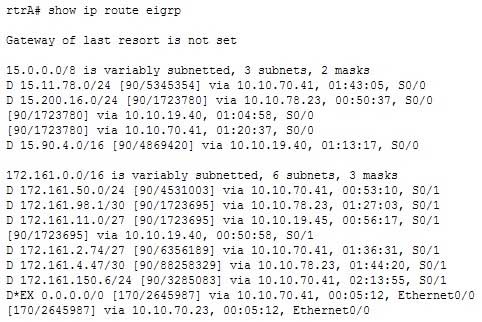
300-410 Part 05 Q16 067 Which of the following destination subnets have equally load-balanced routes? (Choose all that apply.)
- 172.161.4.47/30
- 172.161.11.0/27
- 15.200.16.0/24
- 15.11.78.0/24
- 0.0.0.0/0
Explanation:
The 172.161.11.0/27 and 15.200.16.0/24 networks have equally load-balanced routes. A default route, 0.0.0.0/0, has been configured for load balancing as well. These three subnets are each load balanced on multiple routes. The output entry for the 172.161.11.0/27 subnet is as follows:D 172.161.11.0/27 [90/1723695] via 10.10.19.45, 00:56:17, S0/1
[90/1723695] via 10.10.19.40, 00:50:58, S0/1This subnet can be reached by rtrA through two routes: 10.10.19.45 and 10.10.19.40 next-hop addresses. Both these routes have the same metric (1723695), and so are equally load balanced.
In the output, the 15.200.16.0/24 subnet has three equal-metric routes: 10.10.78.23, 10.10.19.40, and 10.10.70.41. These three routes are equally used to balance the load from rtrA to the 15.200.16.0/24 subnet.
The default route 0.0.0.0/0 is load balanced through two interfaces, as shown in the output:
D*EX 0.0.0.0/0 [170/2645987] via 10.10.70.41, 00:05:12, Ethernet0/0
[170/2645987] via 10.10.70.23, 00:05:12, Ethernet0/0This load balancing of the default route could be tested by using traceroute to any IP address not represented in the routing table and verifying the path taken.
Subnets 172.161.4.47/30 and 15.11.78.0/24 are not participating in load balancing. In the given output, there is a single route (line) for both of these subnets. The rtrA router uses the route through the next-hop 10.10.78.23 to reach the 172.161.4.47/30 destination subnet. Similarly, rtrA uses the next-hop 10.10.70.41 to transmit packets to the 15.11.78.0/24 subnet.
Objective:
Layer 3 Technologies
Sub-Objective:
Configure and verify EIGRP load balancing -
Which command can you use to display the topological database maintained by an OSPF router?
- show ip ospf topology
- show ip ospf database
- show ip ospf [process-id]
- show ip ospf border-routers
Explanation:
The correct answer is show ip ospf database. Partial output is shown below:
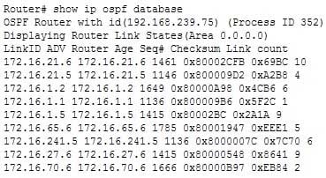
300-410 Part 05 Q17 068 Issuing the show ip ospf database command will show you a summary of the database; however, to obtain details you must use a keyword with the command, such as router, network, summary, or external.
The following commands are available to verify OSPF configurations:
show ip route – displays known routes and from which protocol the routes were discovered for all routing protocols.
show ip ospf – displays the number of times the SPF algorithm has run and the default Link State Update (LSU) interval.
show ip ospf database – displays the router ID, the OSPF process ID, and the contents of the topological database.There is no show ip ospf topology command.The show ip ospf [process-id] command can be used to view the number of times the SPF algorithm has been executed, but not to view the database.The show ip ospf border-routers command display the ABRs and the routes to them, but not the contents of the database.
Objective:
Layer 3 Technologies
Sub-Objective:
Configure and verify OSPF path preference -
Which command can be used to view the number of times the SPF algorithm has been executed?
- show ip ospf
- show ip ospf interface
- show ip ospf database
- show ip ospf neighbor
Explanation:
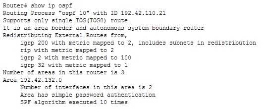
The show ip ospf command can be used to view the number of times the SPF algorithm has been executed, as shown in the last line of the following output:
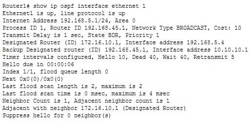
300-410 Part 05 Q18 069 The show ip ospf interface command can be used to view neighbor adjacencies. A partial output of the command is shown below. It will not show the number of times the SPF algorithm has been executed.
300-410 Part 05 Q18 070 The show ip ospf neighbor command can also be used to view neighbor adjacencies, although its output is slightly different from the show ip ospf interface command. A partial output of the show ip ospf neighbor command is shown below. It also does not show the number of times the SPF algorithm was executed.

300-410 Part 05 Q18 071 The show ip ospf database command does not show the number of times the SPF algorithm has executed. It shows the contents of OSPF database. Partial output is shown below:
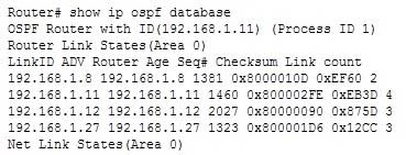
300-410 Part 05 Q18 072 You can make the command output more specific by using parameters with the show ip ospf database command. For example, to view only Type 5 LSAs in the database, you would execute the show ip ospf database external command. Since all Type 5 LSAs are from external networks, this keyword will trim the output to only those types of LSAs. When Type 5 (or external) routes are placed in the database, the next hop address will be 0.0.0.0, which makes it appear as if it is a default route. What this really means is that any traffic that needs to go to that external network will be sent to the router that originated the advertisement (the ASBR).
Objective:
Layer 3 Technologies
Sub-Objective:
Configure and verify OSPF operations -
Which commands will display the other routers with which the local router has established an adjacency with, including hold time and uptime parameters?
- show ip eigrp neighbors
- show ip route
- show adjacencies
- show eigrp neighbors
Explanation:
The show ip eigrp neighbors command will display the neighboring EIGRP routers with which the local router has established an adjacency. It will also display hold time and uptime statistics. In this case, the uptime statistic refers to how long the adjacency has been established. A sample output of the show ip eigrp neighbors command is below.Router2# show ip eigrp neigh
IP-EIGRP neighbors for process 100
H Address Interface Hold Uptime SRTT RTO Q Seq
(sec) (ms) Cnt Num
1 10.20.0.1 Se1 11 22:37:26 28 200 0 2
0 10.10.0.1 Se0 13 22:38:09 19 200 0 4The show ip route command simply displays the routing table and does not provide neighbor information.
The other commands are not valid IOS commands.
Objective:
Layer 3 Technologies
Sub-Objective:
Configure and verify EIGRP neighbor relationship and authentication -
Which of the following statements is TRUE about the communication occurring between rtrA and rtrB in the given exhibit?
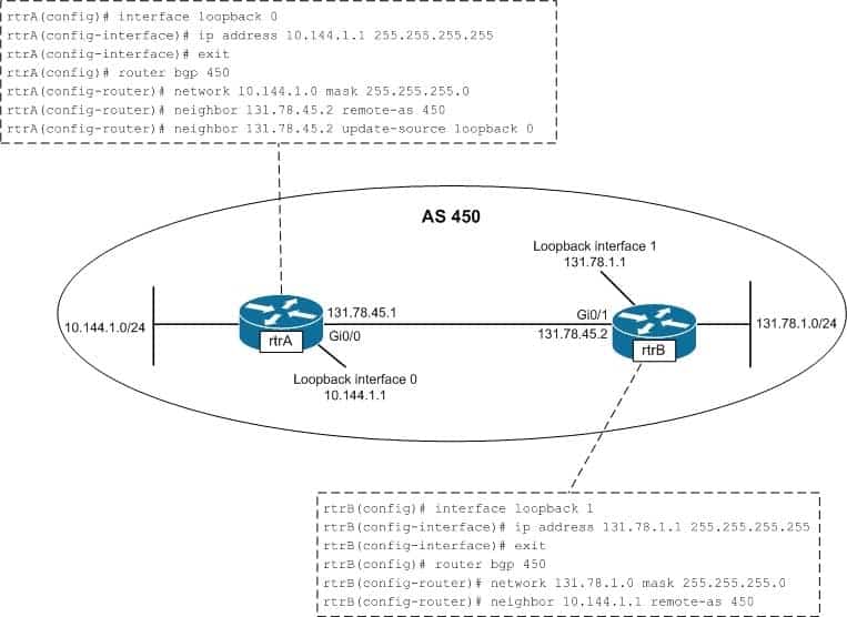
300-410 Part 05 Q20 073 - The only loopback interface used in the communication is the loopback 0 interface of rtrA.
- The only loopback interface used in the communication is the loopback 1 interface of rtrB.
- Both loopback 0 and loopback 1 interfaces are used for the communication between rtrA and rtrB.
- Neither loopback 0 nor loopback 1 interface is used for the communication between rtrA and rtrB.
Explanation:
The only loopback interface used in the communication is the loopback 0 interface of rtrA. The configuration on the rtrA router indicates that BGP is enabled on rtrA in the autonomous system number (ASN) 450. The neighbor 131.78.45.2 remote-as 450 command establishes a connection with the rtrB interface having the 131.78.45.2 address. The Gi0/1 interface of rtrB has the address 131.78.45.2, which is directly connected to the Gi0/0 interface (132.78.45.1) of rtrA. The next line, neighbor 131.78.45.2 update-source loopback 0, specifies that the 131.78.45.2 interface (Gi0/1) of rtrB communicates with the loopback 0 interface on rtrA.In the configuration of rtrB, the neighbor 10.144.1.1 remote-as 450 command establishes a neighboring relationship with the interface having the address10.144.1.1. The loopback 0 interface of rtrA has the address 10.144.1.1. The loopback 1 interface on rtrB is assigned an IP address but not used in establishing BGP connections between rtrA and rtrB
Loopback 1 interface of rtrB only would only be used in the communication between rtrA and rtrB if you configured rtrA and rtrB as follows:
rtrA(config)#router bgp 450
rtrA(config-router)# neighbor 131.78.1.1 remote-as 450
rtrB(config)#router bgp 450
rtrB(config-router)# neighbor 131.78.45.1 remote-as 450
rtrB(config-router)# neighbor 131.78.45.1 update-source loopback 1
Both loopback 0 and loopback 1 interfaces are NOT used for communication between rtrA and rtrB. Only the loopback 0 interface of rtrA is used. Both of the loopback interfaces would be used in the communication between rtrA and rtrB only if you changed the configuration of rtrA and rtrB, as given below:
rtrA(config)# router bgp 450
rtrA(config-router)# neighbor 131.78.1.1 remote-as 450
rtrA(config-router)# neighbor 131.78.1.1 update-source loopback 0
rtrB(config)#router bgp 450
rtrB(config-router)# neighbor 10.144.1.1 remote-as 450
rtrB(config-router)# neighbor 10.144.1.1 update-source loopback 1
Because the loopback 0 interface of rtrA is used in communication, is incorrect to state that neither loopback 0 nor loopback 1 interface is used. To ensure that neither of the loopback interfaces are be used for communication, you would configure rtrA and rtrB as follows:
rtrA(config)# router bgp 450
rtrA(config-router)# neighbor 131.78.45.2 remote-as 450
rtrB(config)# router bgp 450
rtrB(config-router)# neighbor 131.78.45.1 remote-as 450
Objective:
Layer 3 Technologies
Sub-Objective:
Configure and verify eBGP (IPv4 and IPv6 address families)