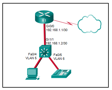
Refer to the exhibit. A Layer 3 switch routes for three VLANs and connects to a router for Internet connectivity. Which two configurations would be applied to the switch? (Choose two.)

- (config)# interface fastethernet0/4
(config-if)# switchport mode trunk - (config)# interface vlan 1
(config-if)# ip address 192.168.1.2 255.255.255.0
(config-if)# no shutdown - (config)# ip routing
- (config)# interface gigabitethernet 1/1
(config-if)# no switchport
(config-if)# ip address 192.168.1.2 255.255.255.252 - (config)# interface gigabitethernet1/1
(config-if)# switchport mode trunk
| Explanation & Hint:
Based on the exhibit, which shows a Layer 3 switch that routes for three VLANs and has a connection to a router for Internet connectivity, the following configurations would be applied to the switch
The first configuration snippet sets the FastEthernet 0/4 interface to trunk mode, which is not consistent with the exhibit since Fa0/4 is associated with VLAN 5, and should not be a trunk if it’s used to connect to an end device like a PC. The second configuration snippet assigns an IP address to VLAN 1, which would not be necessary if VLAN 1 is not used for routing on the switch, and the IP addressing scheme doesn’t fit with the given subnet mask for the VLAN interfaces shown in the exhibit. The last snippet is setting the GigabitEthernet 1/1 interface to trunk mode, which is not correct because this interface should be configured with an IP address for Layer 3 connectivity to the router, as shown in the correct configuration snippet above. |