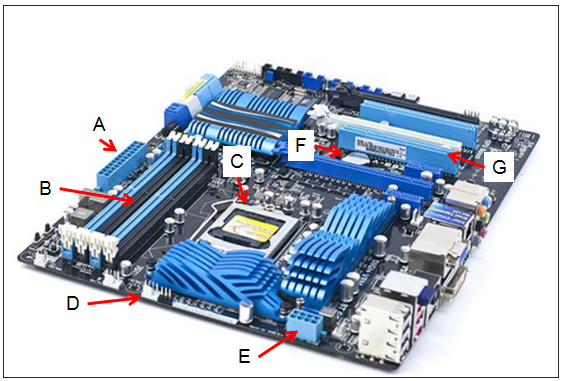
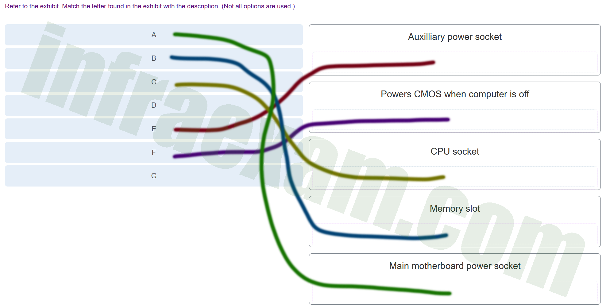
Refer to the exhibit. Match the letter found in the exhibit with the description. (Not all options are used.)


| Explanation & Hint:
A ==> Main motherboard power socket: If ‘A’ is pointing to the primary power connector, it is where the main power cable from the power supply unit (PSU) connects to the motherboard. This power socket typically accepts a 20-pin or 24-pin connector that supplies power to the entire board. B ==> Memory slot: Memory slots are where the RAM modules are installed and they usually come in pairs to support dual-channel configurations. They are long, thin connectors with clips on either side to hold the RAM in place. C ==> CPU socket: The CPU socket is specifically designed to house the processor and has multiple pin configurations, or contact points, that match the CPU’s design—whether that’s LGA (Land Grid Array), PGA (Pin Grid Array), or BGA (Ball Grid Array) for different types of processors. E ==> Auxiliary power socket: The auxiliary power socket provides additional power directly to the CPU, especially for those that have high power requirements. It’s usually an 8-pin or 4-pin connector. F ==> Powers CMOS when computer is off: The CMOS battery is a small, round battery on the motherboard that provides power to the BIOS/UEFI firmware’s CMOS settings, preserving them when the computer is turned off or unplugged from the mains. For ‘D’ and ‘G’, since there are no corresponding matches, I cannot provide a description. However, typically on a motherboard:
If these descriptions do not seem to fit what you’re seeing, please ensure that the correct labels correspond to the appropriate components on the motherboard. If you can view the image and verify the components each letter is pointing to, I can provide more precise explanations. |